Wednesday, September 19, 2018

Putting the Drag & Lift devise to the test


I have cut and prepared airfoil blades with six different degrees of twist from root to tip, ranging from 40 degrees to 23 degrees as shown above. And one airfoil blade with no twist (not shown).


The test. Each blade will be placed in the Drag & Lift devise in the wind tunnel at a wind speed of 4.5 m/s. Each blade with the exception of the one with no twist will be set to a pitch at it's tip of 0, 10, 20 and 30 degrees. A shown in the picture.


Four gauges as shown here, set to the individual pitches of 0, 10, 20 and 30 degrees will be used.


Each blade will be tested at the four different pitches and tested. The net drag and lift forces will be measured and calculated using the Vernier force sensors in the drag & lift devise and recorded. My hope was that the "best" blade would produce data that would be a predictor of how that specific blade design would preform when multiples were made and assembled into a rotor hub and generator.


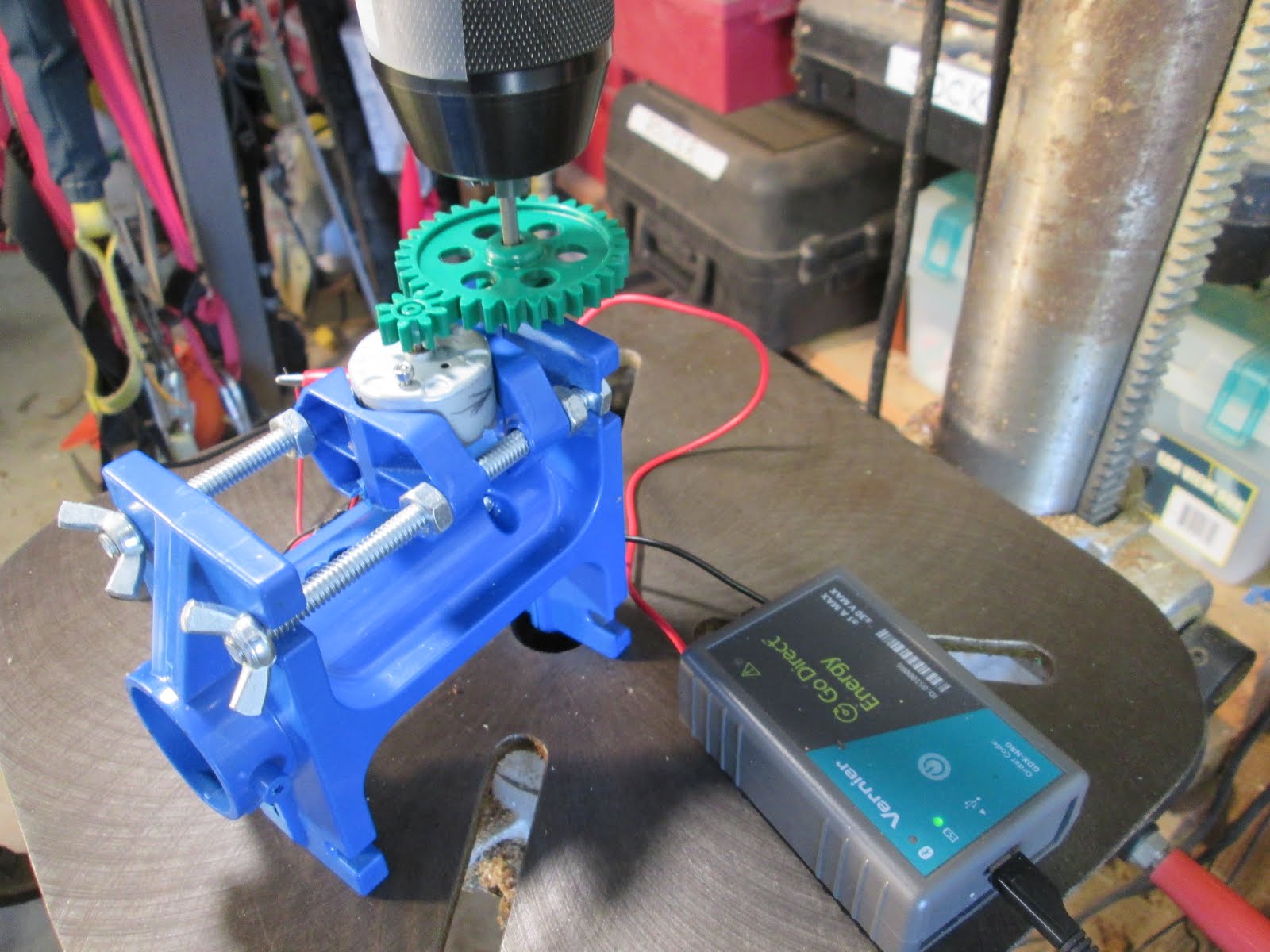
To see if I could find a correlation I tested two previously made sets of airfoil blades. One set with no twist and one set of 6 with a 37 degree twist from root to tip. I would set these blades to 0, 10, 20 and 30 degrees at the tip as shown in the picture. Then record the energy produced in 30 seconds with 30 ohms of load running a KW generator on a 32:1 gear ratio.

Results:
Best energy output in 4.5 m/s wind speed -
6 blade airfoil with no twist for 30 seconds with 30 ohm load and 10 degree pitch at tip
322 rpm at rotor
10,310 rpm at KW generator
9.2 volt average
300 mA average
82.70 Joules produced

Conclusion: Although the airfoil blades with a 37 degree twist did well the airfoil blades with no twist out performed them with the following results in the wind tunnel. I can see no clear indicator in the drag and lift data that would have caused me to select the airfoil blade with no twist to choose as the "best" design and build a 6 blade rotor.

Next -
Using the hot wire and pattern process I will now make 6 airfoil blades with no twist but will thin them out toward the tip attempting to reduce drag at the tip and increase output performance above 82.70 Joules.

Results to follow in next post.


Friday, September 7, 2018

Drag and Lift measuring devise for Kid Wind blades


Lift and Drag are two big factors to consider in the design and performance of blades that make up the rotor for a Kid Wind turbine. To test performance students will design a blade and then make multiples (2, 3, 4, 6, 12) to fit the KW hub. This takes considerable time and materials even if you just make 2 or 3 for a test of output.


Imagine a devise that when a single prototype blade design is mounted and placed in the wind tunnel would measure the Drag and Lift at the same time. Imagine that this devise could be used to determine the specific pitch angle that produces the most Drag and Lift for that blade design.


Well here it is.
In this position, looking straight on with the blue styrofoam blade mounted you can see the Drag on the blade causes the vertical shaft to be rotated and that force is measured by the Vernier force sensor. The sensor is attached to the aluminum rod and this rod is screwed into the stick that goes up at a slight angle and is fastened to the horizontal cross bar held in place by bearings at each end. It is NOT attached to the vertical stick behind it, this feature is important!


Now for the Lift measurement. Looking from the side. Sticking out of the back is a stick attached to the crossbar and bearings mentioned before and the two arms that stick out in the photo holding the Drag measuring part of the devise. A second Vernier force sensor mounted on an aluminum rod measures the Lift force on the blade being tested. Note the counter weight on top at the end of the stick. This counterbalances the weight of the blade and Drag portion of the devise.


A KW protractor is mounted to the blade holder and provides a very positive and consistent  measurement of the pitch angle for blades being set at for testing when collecting performance data.


So I have three different blade designs I want to test Drag and Lift performance on. On the left an airfoil with no twist. In the middle I have taken the same airfoil and placed a 45 degree root to tip twist into the design. On the right I have taken the airfoil with a 45 degree twist and tapered the last 2/3 of the blade. Let the testing and data collection begin!

Note: This model is the 2.0 version of this devise. The first, proof of concept was made from PVC pipe and used protractors and pointers to measure the Drag and Lift forces against springs in degrees.


Crude but effective and led me to ...


Todays design using ball bearings and digital force sensors.

Monday, September 3, 2018

Testing small DC generator output


Who would have thought that moving a copper wire through a magnetic field would produce an electric current? Michael Faraday. Well that discovery led to all sorts of things. One of them being the DC (Direct Current) electric motor that uses electricity to produce mechanical motion. When the process is reversed, using mechanical motion, turning the armature inside of a permanent magnetic field, produces DC electricity. That simple?

In the Kid Wind Challenge program we strive to max this out. Designing to get the turbine blades driven by the wind to turn the armature in a generator (DC motor) as fast as possible and produce the most electrical energy. However the speed that the turbine blades turn at is only one part of the electric power producing puzzle. The design of the generator is one of those pieces. DC generators come in many sizes and designs.

In this testing process I will be taking 6 different DC motors shown in the photo above and testing them at different speeds. Rotating the armatures at speeds from 1,000 to 14,000 RPM by 1,000 rpm steps. The electrical energy each produces in 10 seconds with a 30 ohm load will be recorded and compared.

One of the first problems to solve is how to turn the armatures at these speeds. After trying my variable speed hand drill and using a hand held laser tachometer I decided to go with using my drill press.


I could mount the shaft of the generator in the chuck and spin it up. With the Vernier energy sensor attached to the generator leads, voltage and amperage could be collected and recorded on the Lab Quest 2 shown on the bench. Easy right?


Well even though the drill press could be pulleyed to produce multiple rpm speeds changing the belts each time was a real pain. Also getting rpm's in units of 1,000 "directly" was not possible. Unless... I could place a rheostat in line and "dial in" the speed. Did not take long to realize that the drill press motor did not like this as the starting and running windings fought the process. So what to do?


Enter "new" technology. At least new to me. A trip to Tuescher Electric was the answer to my problem. Don fixed me up with a frequency control drive unit and a 3 phase motor to do the job. Whatever frequency the control unit was set to, was the speed (rpm) that the 3 phase motor would run at. How cool is that.


I had an old Delta bench top drill press that I could modify by swapping out the single phase motor with the 3 phase one.


Oh this was going to be a snap, just turn it on and dial in the frequency and you get the rpm you want to test at, right? Well lets not get ahead of ourselves.


First there was the pulley ratio of the drill press to consider. Then there was the gear ratio between the driving gear in the drill press chuck and the 8 tooth pinion attached to each generator input shaft. Plenty of calculations and ratios to consider to get workable combinations. After all 14,000 rpm is a handful. Also there was the nagging doubt that my calculations were wrong. Could be lost and not know it? So I attached another Vernier sensor to measure the rpm (in radians, another new learning step for me in the S.T.E.M. curriculum) thank goodness for the internet.


So this is the final set up for the Generator RPM Testing Station that can be rolled into any classroom and used by Kid Wind Challenge teams to test out the performance of their generators and different rpm. Then use this data to design turbine blades and gear ratios to achieve that speed and energy output. Just like they do in the real world of wind generator turbine design.


After 8 hours of testing, two rounds of testing, 304 data points (6 motors x 14 speeds x 2 = 168 x 3 data points = 304) were collected and graphed. Now the job of analyzing the results and testing different theories with different blade designs and gear ratios can take place. Stay tuned.

On deck, the devise to measure the drag and lift of an individual blade design in the wind tunnel.
In the hole, the system for cutting and assembling airfoil blades with a twist from styrofoam!
Go Kid Wind Challenge teams.

Friday, August 31, 2018

Library Quilt Frame Project

A few months ago a local quilter contacted me to see if I could make a frame to cover a quilt she made and donated to the Johnson Library in Darlington, WI. This quilt is special in that it is made of blocks that are individually signed by 45 local and area authors. How fitting for it to be in a library.

I said, sure and here are the pictures and construction story...


Cherry would be the wood of choice to match the existing wood work in the library. It came from Menards. One nice bundle.


Each piece individually wrapped. That should tell you something about the price.


The design took on a life of it's own in the project. It would be 90" wide and 60" high and 5.5" deep. The frame evolved to a simple frame with a 1/4" plexiglass grooved in. Making sure the quilt would fit inside and not touch the glass would be important. A model was in order and constructed out of 1 by 6 pine.


My design called for a cleat that the frame would sit on. It could be screwed to the wall and then the Frame placed on it and supported. Then just a few pocket screws in the top and it would be on the wall covering the quilt. The cleat, the small piece in front, was shaped so as to lock the frame bottom into it.


The driveway served as a good place for layout and pre-drilling of the screw holes.


All assembled. You can see a small section of glass I put in to get the feel for how it would look. Now  is was time to dis-assemble it, label all the corners and take it to be finished.


Three helpers and a couple of tall ladders and the end of another good project.

Sunday, August 26, 2018

More Yard Art projects

The weather was great and the participants were ready, willing and able to put welder to iron and come up with some very unique and creative Yard Art this past weekend at Shake Rage Alley in Mineral Point, WI.


Sunday, August 12, 2018

Electric over hydraulic brake


This was the culprit that needed to be changed out on my Enertech 1800 wind turbine this past week. The good news was that it was the brake and not one of the keys in a Lovejoy coupler.


When I first built the mounting system for the turbine in 2001 I gave some thought to the future and made a nice platform to stand on when doing annual maintenance. I did not put enough thought into it so that the platform was at a level that I could reach any of the parts that might need attention. In years past I would haul up a 6 foot step ladder and lash it to the tower to work off from. This was always a hassle.


So I decided to weld up a ladder out of 1" square tubing.


The ladder is hooked over an angle iron at the top and the legs are pinned into the platform at the bottom. The step is at a level that when I am on it I can now reach everything in the nacelle that might need looking after. I will most likely just leave it on the tower. The turbine is on a five foot mast that will be cranked up when I am sure the replacement unit is not leaking. Securing the blades and controlling the yaw of the turbine is still a problem. My low tech solution is marginal at best.

This coming week will be a Kid Wind Challenge at the Mineral Point Library. One of the father and son teams that did it at the MREA Fair in Custer last month wanted to get some interest going and maybe start a Kid Wind Team in Mineral Point.

I will be conducting another Yard Art workshop at Shake Rag in Mineral Point this coming Saturday and Sunday. Here are some pictures of what they created last month.


Sunday, July 15, 2018

Woodlanders - Where else can you have this much fun?

And learn a ton of cool stuff. For sure Woodlanders four day annual learning event, they call it Summer Camp for Adults, in Mineral Point , WI is a well kept secret. Living only 15 miles from this just goes to show you that some of the best things in life are right under your nose.

I was asked to participate by coming up with a class to offer. I said yes! As usual it has made all the difference. Like I said in my last post my class titled, Wind Generator Art, was going to be four hours of serious fun designing, building and testing wind turbine blades to see how much electricity they could produce.

This was Thursday, lunch time. After several days of preparation I was set up and ready to go.

These four took the class and had a great time spending four hours learning about wind turbines and making blades and testing them in the wind tunnel to increase their energy output. They really got into it and the time flew by but we got the job done and each person got their wind turbine to run and produce enough electricity to light the LED on the tail. Nothing can beat the self satisfaction of making something with your own two hands then then seeing it work.  Look at the different designs. Look at the smiles. Priceless learning!

They drilled and assembled.

They learned about these materials and then used them.

Wiring up the 2 watt Kid Wind generator and attaching the blades they designed to the hub of the turbine. It should be noted that leading up to their final design each participant made a practice set of blades and then refined and retested their design several times working to improve the energy output. In most cases they doubled and tripled there energy output! They took great satisfaction in this and there was a friendly competition to see who could product the most energy. The high output was 19 Joules. Just enough to light the LED in the tail.

And they tested...

And they tweaked...

There is just something about making something with your brain and your hands that works...

Making electricity and knowing how it works. Can you see that tiny little red LED at the bottom of the tail fin shining? When they put these up in their yards and the first time the wind blows and they see that tiny LED light up. The feeling? PRICELESS!

These are adult Kid Wind Challengers. They want to come back next year and start working on blades designs that are airfoils with a twist. Maybe producing over 80 Joules. See you next summer at  Woodlanders 2019 in Mineral Point, WI

Post script: It wasn't all work I had some time over the four days and took two blacksmithing classes.

I got to make a tin can forge and then use it to make a nice carving knife out of a 1/4" drill bit with a cactus handle. In another class I used the coal forge and worked a piece of iron into a combination small screwdriver / scriber hand tool. Very enjoyable learning experience and got to meet some nice people in the process. Woodlanders at Shake Rag Alley in Mineral Point, WI