Wednesday, June 30, 2021

In Floor Heating of Cabin #6

 Decided to go all in as they say and put electric floor heating in the cabin. As the cabin is built on a concrete slab this should make a big difference in the winter comfort level and enjoyment of the cabin.

I decided to lay down 3/4" of foil faced insulation on the concrete floor as a thermal break to the cold.

Next the system I choose comes with a mate that is laid down and the heating resistance wire is snapped into. I comes in 3 foot wide rolls and cuts easily with a utility knife.

OK now with the mate down it was time to start snapping in the heating wire. For this system the wire is spaced every three cones.  There are some rules for this and every system is different. For this one no wires can cross and the length cannot be cut. So you have to order the exact length for the area you are heating. My supplier did all this and it worked out just fine. The sensor wire for the system cannot cross over any wires and should be located near the center of the room. In most situations this type of floor is used where ceramic tile is used for the finish floor. I wanted to use laminate plank. 


Nice. Finished laying the heating wire. Now to place the two sensors and their wires. They send two sensors so there is a back up should one fail. For me it would be a big pain to pull up the finish floor. For a ceramic floor it would be impossible. So two is better than one. However the wiring for all this is another learning experience. A lot of online video to help and the second time will be easier.

The final step would be the finish flooring. I used snap together vinyl laminate. This required a thin layer of foam to be laid down over everything. Snap it together leaving a 3/8" gap for expansion and you have a nice durable cabin floor in a couple of hours.

And there you have it. You can see the main power service panel. The cold end of the heating wire had to be routed up to the thermostat along with the 220 volt supply power and two temperature sensor wires. This all terminate out of view in this picture at the top of PVC pipe where the control thermostat is located. This company is pretty strict about testing the heating wire and sensor wires for resistance and shorts before, during and after installation. But all is well. Will wait until fall to make the finals connections and put the floor to work.

Well I hope you have enjoyed the journey and process of designing and building my Hand Hewn Log Cabin #6 as much as I have over the past year or two.


Wednesday, June 23, 2021

Treehouse Phase V - The Enjoyment Phase


OK so with the reassembly phase complete it was time to put on the rubber membrane roof material. It was a calm day so I took advantage of it.


Now if you have been following this process you remember how the membrane was laid out in place on the roof the first time. The process was a struggle even when there was the possibility of working with this sheet of material from the ground. So when we took it off I carefully folded it like a giant pie crust and marked the starting location with detailed instructions for unfolding. This had to go exactly in place the first time when working only from the hatch opening in the roof. I loaded the 80 pound bundle on the elevator and crossed my fingers. It was a success! The loose edge s would be pulled down and wrapped around the fascia then stapled to the inside. Then a 1x2 strip would be screwed over the staples and screwed down to clamp it in place.

With the roof membrane down and secured it was time to bring up the windows. The 60" x 60" sliders were a tight squeeze for me and the elevator opening. But it worked, "just as I planned it".

And there you have it from the back side looking East.

Here it is looking South.

Had a nice glass of wine with the wife in it to celebrate and hung some Christmas lights for mood lighting. I knew from the start this project would be a challenge and a learning process but I tried not to think to much about it and just plunged forward. For every problem there was a solution and this is the proof of that. I have to give a big shout out to my good friend Jerry for without his help and many ideas throughout the process I could not have done this. My advise if you are going to try something cool like this is make sure you have a guy like Jerry around.


Tuesday, June 22, 2021

Reassembly of the hexagon and roof frame


With the floor done it was now time to begin to reassemble the corner posts that would support the hexagon roof frame. The elevator would come in very handy for this task. Here are the corner post loaded and ready for transport to the top.


OK, The corner posts are attached to the floor rim joist with four GRK screws and then a 2x12 header placed between them at the top. The header is fastened to the posts with 4" wide nail plates and screws. 


Here the nail plates that hold together the posts and headers can be seen. Not visible are the hurricane straps that are wrapped around and over the rafters and fastened to the outside of the header. Also in the picture, between the nail plates is the temporary blocking  at the end of each rafter subassembly section that helps position it. This was key to the assembly process for a roof frame like this. To the right can be seen the upper pulley that was used to bring up each roof subassembly frame. This could not be brought up in the elevator because of their size.

The rigging of a second class, moving pulley, made the task of lifting up each of the roof frame subassembly a snap. Two guide ropes were attached to the bottom corners of the frame and ran through junk brake rotors on the ground. These kept the frame from twisting around as they were raised to the top. Also the extra length of the sling from the pulley to the frame gave me the slack I needed to lift and twist the frame up onto the floor deck. Made the whole thing a one person process.


Things are really starting to take shape now. The first two sections of roof frame are up and in place. The 12 sided center pin where the rafter sections meet at the top is held up by a set of temporary supports.

With the roof rafters in place it was time to sort out and pair up the 12 roof sheathing pieces. This was a puzzle and even though the parts should be the same there was some "uniqueness" to the individual parts that came about in the process of making the six sided form. Anyone that has ever built a Gazebo knows what I am talking about. If you haven't you will the first time you do one.

Pairs of roof sections could be loaded on the elevator and brought to the top. C-clamps were attached to the edges for grip and helped to get the pieces up through the roof frame and in place.

One sixth of the "pie" was on. I would work my way around the roof going up from the inside and screwing down each piece of 1/2" OSB to the rafters.

No doubt about it. With half of the roof covered progress continues and should be having a drink high above Cabin #6 in a week or so. You can see two of the windows for the treehouse leaning against the cabin.


Thursday, June 17, 2021

The Elevator - goes "Up"

So in this phase of the project the solution for getting up into the treehouse will be solved.

Plumb bobs were dropped from the top of the floor to locate exactly where the guide rails for the elevator would need to be dug. Short sections of treated lumber were used for the portion that would be in the ground. Gravel would be used to fill in the holes when finished.

The cross section of the guide rails would be built up like this at the bottom for support strength and stability.

A 2x6 is layed on top of a 2x4 to form the first rail leg. This had to be straight in both X and Y planes.

With the 2x6 and 2x4 "T" assembled for both rails it was time to attach the garage door track. This was made of two pieces arranged so that the rollers on the elevator cage would be trapped inside the track. 

The rails were rotated 90 degrees so the garage door tracks faced each other. Then recycled 1x6 treated deck boards were attached every 24" to tie the two rails together and provide an escape "ladder" should there be a problem with the elevator or hoist. I also gave the wood a coat of finish while it was on the ground.

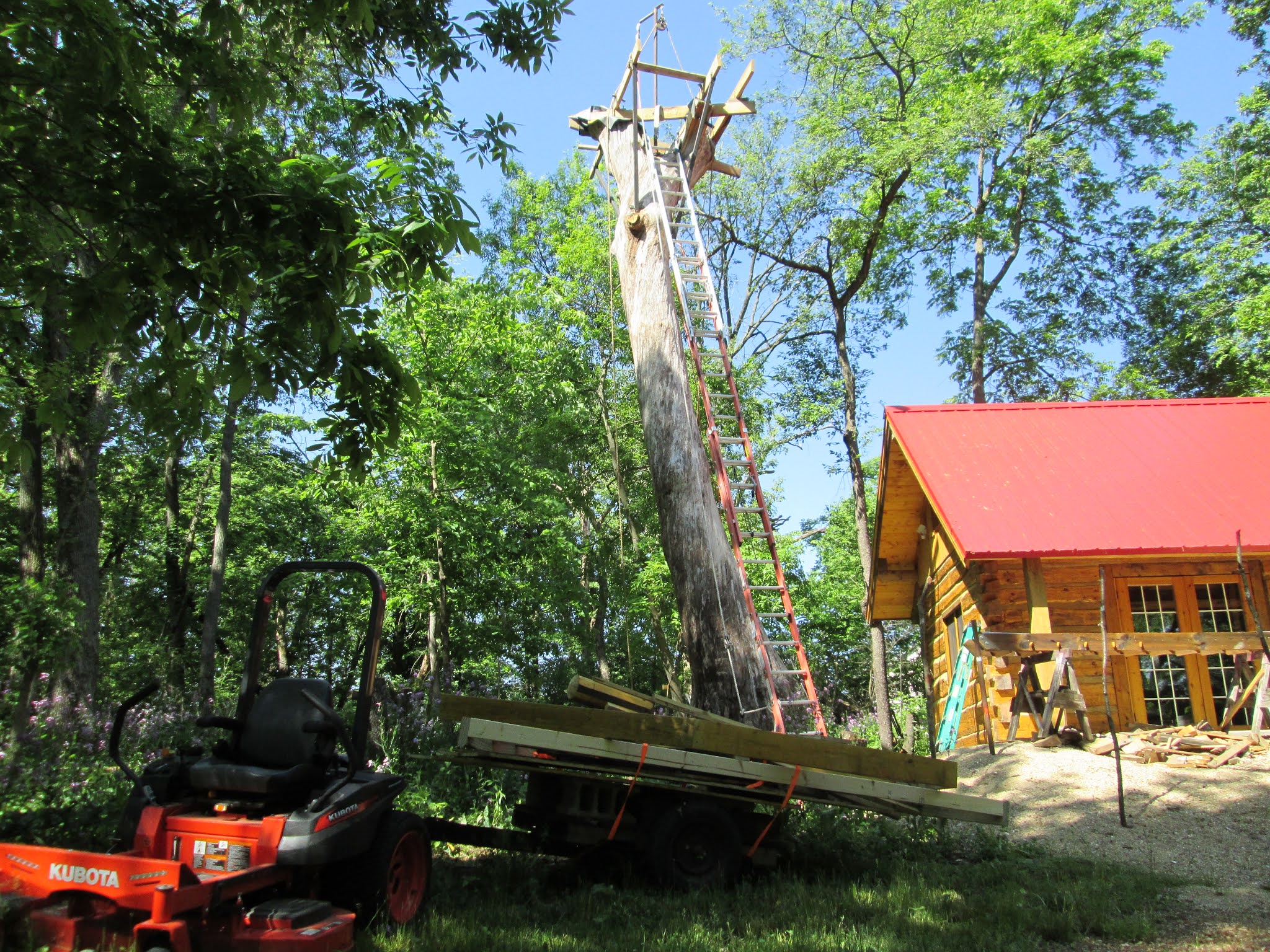
Rigging for the lift would be another challenge. I decided to harness the top in two places with a cable then attach a sliding snatch block that could move along the harness as the assembly was raised. This would make two lifting points and take some of the stress off the rails during the lift. Not shown but, equally important was a set of come alongs attached to the bottom ends of the rails. These held the rails and prevented them from sliding forward as the assembled rail system was lifted. It did the job and worked very well.


A worm drive winch left over for a bridge raising was used to raise the rail assembly. It was anchored to a section of the 2x8 Oak support structure. The hand crank was replaced with a Milwaukee Hole Hog drill to do the turning. 

The first 45 degrees of lift were the hardest and you could tell by the load on the winch. Two helpers maned guide ropes on the top end just to make sure the rail assembly did not swing for some reason during the lift.

Well as the casual observer would say, "That was easy".

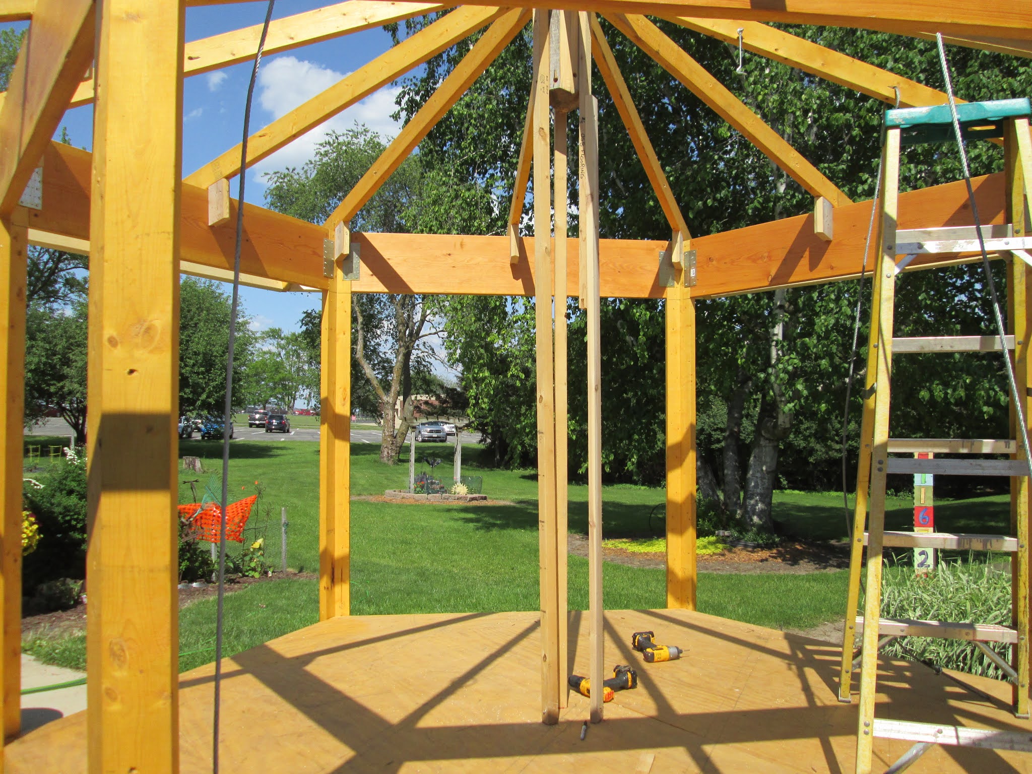
With the elevator cage in place and the hoist attached it was time for a test run. A load of 350 pounds of concrete blocks would do the trick. Note: the platform sticking out in front is a temporary support to hold pieces of the treehouse that will be brought up to the top for assembly.

And there you have it. First load, 350 pounds of concrete blocks raised up 30 feet to the floor of the treehouse. Now I can remove the ladder, finish the floor and begin the re-assembly of the treehouse. 


Monday, June 7, 2021

Floor Deck in place


So weighing in at about 75 pounds per section rigging and lifting the floor frame halves to the top in the correct orientation and getting them to clear the braces and supporting structure would be no small task. The question is how would you rig the lift? As shown here? We will call this Rig A

Or Rig B?

Or Rig C? If you said C then we could have used you when we did this.

After a few fits and starts the two halves where in place and screwed together. Although we had to resort to using a come-along to power the second half up and over the supports.

To help handle the upload forces that will occur the floor joists are secured to the main beam supports with  metal straps like this.

The 3/4 plywood flooring was then glued and screwed down to the floor joists.

And this is what it looks like from the ground. The last piece of flooring has to be left off for now to allow access so I can work on installing the elevator system. At that point the ladder will come down and the elevator will be used from then on to bring me and the parts top the top. Should be more fun than climbing the ladder.


Friday, June 4, 2021

Treehouse packed and ready to roll


The first step in dissembling the treehouse was to remove the hatch and rubber roof membrane. With this done I could begin to take off the roof sheathing. The upper portion of the treehouse would be stacked on the trailer shown on the left. The floor and floor framing would be put on another trailer.

With projects like this it is best and easiest to do any painting or staining before you assemble the project. So here are the roof sheets laid out in the shed where I could roller on a nice coat of white paint for the ceiling. The same treatment was given to the bottom side of the sheets of plywood flooring.

So with the roof sheathing removed it was time to think about the rafters and how they might be kept in some sort of sub-assembly. The solution was to add a second set of block stops to the mid rafters. Then I also installed three leg supports on the center plug and marked their location on the floor.

Each set of primary and secondary rafters would be screwed together at the top. Then one end of the fascia would be unscrewed, leaving it attached to the lower ends of the primary/secondary pair. This triangular segment was then removed.

This unit, one of six was easy to remove. Reassembly would be just as easy by hanging the unit on the header between vertical posts and then rolling it in place.


All six of the roof units stacked and ready to load.

Removing the headers and main posts was pretty straight forward.

This is a pretty good shot of the loaded trailers. On the right are the main parts. Stacked in the order they will be needed. On the Left is the trailer with the floor system. Here you can see how the following joists and rim joist were split in half. Each half of the floor frame will be raised up as a unit. This should make for easy setting of the floor on the support already in the tree.

And the arrival of the first phase of the treehouse reassembly. After the floor is in place then I will go to work putting in the elevator. For this phase the rope and pulley system will be used to get parts to the top. The elevator will be used to bring the rest of the parts up and finish the fun!