Monday, December 11, 2017

Wind Tunnel Shroud for 44" diameter Barn Fan

Having a good source of wind to test Kid Wind students generator designs in is a big plus. Many schools have one of these large barn fans. This post will walk you through the construction steps for building a removable shroud that can be easily attached and removed from a 44" diameter fan like the one shown above. The design requires minimal tools and wood working skills. Cost less than $100. Takes up less that 4 sq. ft. of floor space when folded and takes less than 1 minute to attach and setup for use! It does take several hours and some patience to cut and assemble, but could make for some quality time or a worthy project for a Kid Wind Team.
It is important to note that the wind tunnel shroud is attached to the INTAKE side of the barn fan. Doing it this way will insure a less turbulent air stream of about 12 mph for testing student's wind generators.


Lets get started...

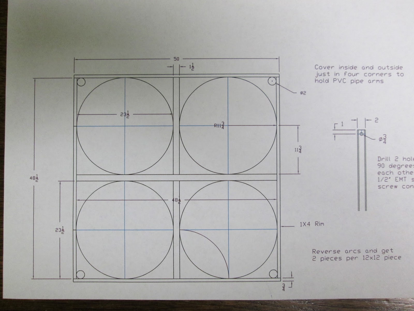
First thing is to read and study the blueprint and all the notes to get familiar with the design details.


BACK FRAME
Cut and assemble the Back Frame first. This will be the part that attaches to the barn fan. The Side and Top Frames will be hinged to this.

Cut List -
1 - 2 x 8 - 51" Long
1 - 2 x 6 - 48" Long (Note: This is ripped from the other half of the 10' - 2 x 8 board)
2 - 2 x 4 - 48" Long
1 Piece if 3/4" CDX Plywood - this plywood is attached inside the frame and then the hole for the fan played out and cut. You will also have to notch out an area for the wheels on the fan to fit in.


Back Frame Drawing

Cut and assemble the TWO Side Frames

Cut List for TWO Side Frames -
4 - 2 x 4 - 48" Long
2 - 2 x 2 - 40" Long

 Side Frames and Top Frame Drawings

Cut and assemble One Top Frame

Cut List for ONE Top Frame - 
2- 2 x 4 - 36" Long
2 - 2 x 2 - 51" Long


Attaching 8 mil plastic to frames

Heavy picture frame mate strips are hot glued to the 8 mil plastic and then rolled so that the plastic is wrapped around the mate strip. Then the strip is stapled to the outside of the Top and Side frames.

Since the picture frame mate material is thicker than tag board I used a band saw to cut the 1/2" wide strips I needed.

Working from the middle out the first side is stapled through the plastic and mate strip material. Then do the same on the opposite side drawing the plastic tight. Repeat the process for the remaining two sides.

This is the finished product. By the time you do three of these you should have the hang of it!


Assemble the TOP FRAME to the BACK FRAME with hinges mounted on the inside as shown. It is important to attach the top frame first because it places the hinges and they can now be measured so clearance notches for them can be cut into the top of each SIDE FRAME.

Locate, mark and cut the clearance notches for the hinges in the FIRST SIDE FRAME. Then attach the SIDE FRAME to the BACK FRAME with hinges on the inside.  HINT - Rotate the assembled frames around so that each time the plastic covered frame is on the floor when the hinges are attached. Locate, mark and cut the clearance notches for the hinges in the SECOND SIDE FRAME and attach with hinges.

And here is what you should now have. Notice I have added a pull strap to the FIRST SIDE FRAME. This is needed to pull the frame out when setting it up. NOTE: In this photo the 3/4" plywood brace where the wheel will be is on the wrong edge of the 2x4 and no notch for the wheel has been cut yet. Also note that the triangle pieces are now a single piece of 4' by 4' CDX plywood.


A hole was drilled for the pin (a 16d duplex nail) that holds the SIDE FRAMES in place when swung out. NOTE the FIRST SIDE FRAME is short of the TOP FRAME this is necessary so that the FISRT SIDE FRAME will fold completely inside for storage.


Also I have added two 2x4 feet to the bottom of the BACK FRAME to stabilize the unit when it is folded up for storage. NOTE: These should be 2 x 4 scraps, longer and on both sides. The 2x2 piece on each side acts as a handle. There is a removable pin that holds the SECOND SIDE FRAME in place. The draw hasp catch has not been installed yet in this photo but they will go right below each 2x2 handle.


Here the clasps are mounted and the shroud is pulled tight to the barn fan. This shroud could be used on larger or smaller diameter fans you would just have to modify the size of the corner braces and alignment for the clasps. Turn buckles could also be used instead of clasps.


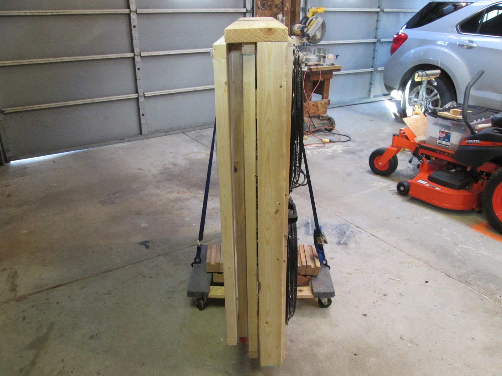
And here you can see the shroud disconnected from the fan, folded up and neatly stored out of the way under a set of stairs ready to be pulled out for the next wind tunnel testing of a set of blades and wind turbine for a Kid Wind Challenge.


I welcome any questions or comments on this design if you are making one of these. Thanks

Tuesday, November 21, 2017

"Step by step" cabin

Added on a nice porch to the cabin and it looks great. Nice touch. Gable ends will be covered with vertical boards from another salvaged building Lynn saved.

For the porch posts Lynn used logs salvaged from an old family farm barn. The rafters came with the original cabin logs. The roof boards were cut from some trees off the farm. Going to be able to enjoy a nice cup of coffee from this porch.

Now for the "step by step"
To get into the loft Lynn wanted stairs and not a ladder. Right off the bat I said no problem. (One of the three biggest lies. 1. The check is in the mail. 2. I'm from the government and am here to help you. 3. No problem, this will only take a minute.) As the cabin developed I could see more clearly what I was up against. A door and window on one wall. A window on another wall. And the floor joists in the loft. As I played this out in my mind and several sketches my brain was racked. I knew I would need a landing and the total rise for the stairs and each run. I decided to make a cardboard pattern and this showed me some of the details and finer points of the construction I had to consider.

After a good nights sleep I decided it was time to cut wood! Lynn's husband Steve had some since 2x12's that he saved from a trailer he redecked and they were perfect. I layed out the first stringer as though the stairs had no landing using the two runs. Then layed out where I would need to cut them off. Using the two pieces I had patterns and cut the mating pairs of stringers.

It took a couple of hours but they fit well and cleared the windows and door.  Building the box frame to support the landing took the most time and then locating the vertical post that was need to support the loft floor joist that had to be cut off was another head scratcher.

Here you can see the post where it supports the floor joist end. Floor boards for the loft will come next.

And there you have it "step by step". Progress continues with a bit more work to do (floor, ceiling, windows, gable ends, chinking and trim inside and out). I would say that cutting steps like these were a challenge and I learned a lot. Stairs in the next cabin will be "no problem"!

Wednesday, November 8, 2017

Kid Wind wind tunnel plans Update Design 2.0

This post will provide the plans, instructions and materials list for building a 4 fan wind tunnel with a 48" opening similar to the type used to test student built wind generators in the Kid Wind Challenge competition. It is important to note that the wind tunnel shroud is placed on the INTAKE side of the fans. Doing this will provide a less turbulent air stream of about 10 mph for testing student's wind generatorsNOTE: This is picture of the old design

Old design shown here.
Here you can see the finished product. This photo will be used several times in these instruction and will be helpful if referred to to study details and answer questions that will come up during construction. Note the large paper clips on the 1/2" EMT tubing at the opening. Note the 1" square blocks on the ends of the 1 1/2" PVC pipe arms that the 8mil clear plastic is wrapped around. Lastly notice the two large hand clamps in the upper left of the photo holding the plastic sheet where it joins together. Note: No PVC pipe is used in the 2.0 design so no holes will be needed in the 4 corners.


HERE is the new 2.0 design. Simpler. More room and student/teacher friendly set up in less than 1 minute! No PVC pipe no EMT conduit no binder clips no wrapping of plastic no setup tools required.

Here is the drawing. If you are a go-gitter like me and like a challenge than this is all you will need and go to it. If you have questions or need a few more details read on...

Here the materials list - Menards, Ace Hardware and Northern Tool were my sources for them.
- 1 -  3/4" handy panel 2' x 8' that will be ripped in half and cut to make the arcs in corners.
- 50 - 2" pocket screws
- 1 -  2x4 - 10' long
- 2 - 1x4 - 10' long
- 14 feet of 48" wide 8 mil clear plastic sheet 2.0 Design only covers three sides.
- 1 - 4 plug power strip with on/off switch
- 4 - Item Number 47051 Description  RTN 22" Tilt Cooler $99 each. Northern Tool

NEW DESIGN 2.0 Materials for shroud frames - Rough Lengths

- 1 - 2x8 - 5 feet long
- 1 - 2x6 - 4 feet long
- 4 - 2x4 - 8 feet long
- 1 - 2x2 - 10 feet long
- 2 - 2x2 - 8 feet long
- 6 - 4" door hinges and screws


Tools list -
Skill saw
Assorted drill bits
3/8" hand drill
Drill press
Screw gun
Pocket screw cutter and screws
Band saw or saber saw


Remember what you are building? Lets get started. Remember no PVC or EMT Conduit in New 2.0 Design

Well that was easy. If you got this far you know what I am going to talk about in the next few photos. If not then read on...

First you will want to rip the 2' wide 3/4" plywood into two 12" strips. Then cut twelve 12" squares (that should leave you a 4' long piece for the storage rack later). You are going to want to make a compass that will draw two 11 3/4" arcs on each 12" square piece you cut. These will be the fillers to go around the fans.


Then you will want to look at the print and cut the 2x4 and 1x4's the correct lengths. Using pocket screws assemble the 2x4's to make one half of the center cross like in the photo below.

You can attach the four plywood pieces (with pocket screws) as shown above and check the fit of one of your fans to see how you did. Note: these fans come with two plastic  pieces for the tilt and lock mechanism. I removed them and it is a chore. You could leave them on and just place them in the corners at a diagonal if you want.

So moving right along. You have finished the other half of the cross and corner pieces. Now study the  next photo and we will discuss the top and bottom pieces.

In this photo you can see that the outside corners have two pieces of plywood. Also understand that these corner pieces are ONLY attached to the top and bottom 1x4 pieces (NOT THE SIDE PIECES). They ARE NOT attached to any 2x4 piece. Later when the fans are put into the openings. Then you will screw them into the side 1x4's to secure them. Do not worry about attaching them to the 2x4's.  Note: You will have to make a small notch in the four pieces of plywood at the center cross to allow the power of each fan to be routed through. You are looking at the back side of the wind tunnel and the power strip should be mounted right in the center cross area. Also for stability while building it is good to place the 2' piece of PVC for the axle in the lower hole.

NEW DESIGN 2.0 Simplified and Improved - read on

Lift up top frame then swing out each side frame. A simple pin in the front corners holds each side frame in place. Each plastic covered frame is hinged to the main fan box.

NOTE: You will also need to locate, layout and cut out some clearance notches in the tops of each SIDE FRAME so that when you swing the frames in for storage they will clear the spines of the hinges holding the TOP FRAME.


The key to construction is to extend each casing that the frames hinge to so that when folded each one will clear the other and fold flat. In this photo you can see that the top frame casing a 2x8 (extended the most because it has to allow for the other two side frame thicknesses) that the hinges are attached to. Facing you in the photo is the 2x4 casing used for the first side and hinges. The other side uses a 2x6 casing.


The drawing might be helpful. You have the main fan box in black. The left and right side frames in green and the top frame in red.

Here it is the NEW and IMPROVED 2.0 design. Easier to move, store, set up and take down!


ATTACHING THE 8 MIL PLASTIC TO THE FRAMES

The 8 mil plastic is attached to each frame by first hot gluing a strip of heavy picture frame mat material to one edge. Then rolling the strip to wrap the plastic around it. Then stapling through the plastic and mat strip to attach it to the frame. Next do the same thing on the opposite side, pulling the plastic tight. Repeat the process on the remaining two sides and you have one frame done.

I used a bandsaw to cut the 1/2" wide strips of heavy picture frame mat material.

Staple the plastic wrapped strips about every 2" along the outside surface of the frame edges.

Buy the time you get done with the third one of these you should have the hang of it!


If you have any questions or comments just let me know and I will happy to help a fellow Kid Wind'er out.


Thursday, November 2, 2017

Roof on Rear cabin

Steve and I got a little Amish help from Henry and Isaac and we got the rafters up, rake ends on and one side sheathed. Good days work.


The next day we put the sheathing on the other side.

The roofers came and made short work of the job finishing up the roof.

VERY NICE. Let it rain, let it rain!

Hung the 4" thick cabin door.


Lynn had some old 8" logs that were taken from an old barn that was in the family. She wanted to use them in the cabin somewhere. I hued one side flat and used them as floor joists for the loft.

Things are moving along nicely. Steve (Lynn's husband) and some helpers should get the porch floor built this week. They might also get the ceiling insulation up and maybe start putting the rough sawed  boards on the ceiling. Gable ends will be sheathed and boards put on as soon as the Z flashing get in. I will now get to work on laying out the stairs to the loft.

Sunday, October 22, 2017

Down in 4 hours, Up in 8 !

Well this went, well! Took Lynn's cabin down in 4 hours and loaded the logs on two trailers on Friday night. A good crew and a Bobcat with a boom mounted on the forks made short work of it.

 Took a lot longer to plan, cut and assemble the cabin but that's the way it is with most projects.

 9 am Saturday. Great weather and good day for cabin building. Here is the view that Lynn with have. First step was to lay down sill seal and the treated 2x6's that the logs will sit on. A layer of 1" styrofoam insulation will go down over the concrete and them a layer of 1/2" treated plywood for the sub-floor.

Here is Lynn putting some fiberglass insulation in the area where the half-dovetail surfaces will meet. This will insure a tight seam and eliminate drafts.

Lynn's dream cabin project is a family affair. Her daughter and sister were in charge of selecting and rigging the logs so husband, Steve could bring them to the cabin wall on the skid steer forks.

This process continued, round after round. By noon we had the window frames set and the first trailer unloaded.


As the height of the walls grew the boom was used to lift the logs up. This was trickier that it looks and required a bit of thinking and planning as each log had a specific inside and outside to it. If you look at the end of the log you can see the "playing card" system I used to ID each log end and it's specific round and corner placement on the cabin.


Son-in-law, Lucas and I worked on the walls setting and pinning logs to knit the walls together. You can see the 1 1/2" pin just to the right of the window, between the two top logs. This was done all the way around the cabin on the full length logs. Pounding in the Oak pegs for this was a challenge even when we greased the pegs. We also had to drill several holes in the logs as we went to allow for wires to be ran for electrical wiring that will go in later.

And here's the crew after a good day of hard teamwork completing phase 2 of the cabin project. A hundred  years ago this crew could have held its own with any family building a cabin to live in on the farmstead.

So, next up will be re-framing the roof and getting it ready for sheathing and shingles. Also I will go back to work inside installing the floor of the loft and cutting the stairs to it. Still plenty of serious fun  to be had before the family can move in for the winter and gather around a nice cozy wood stove fire!