Sunday, December 18, 2022

What do you see?


A new year requires a new project. So look at this picture. I ask, What do you see? ...  Some may say a nice winter scene. Or an ax throwing target. Maybe a sculpture made of old junk parts. Perhaps boards nailed to a tree. What do you see?


Lets zoom in a bit and eliminate some of the distractions. Now, What do you SEE? Many will say a woods with a dead, broken off tree and they would be correct. Because that's what it IS. But, if we use a little bit of  imagination and think out of the box it could be...


A very cool lookout tower/treehouse. Can you see the spiral stairs going around the tree trunk. Can you see yourself going through the floor opening. Then sitting on a bench seat wrapped around the tree looking out over the woods. 

Well follow along with me and over the next few months I will show you what I SEE. Doing this has made all the difference for me in my life.

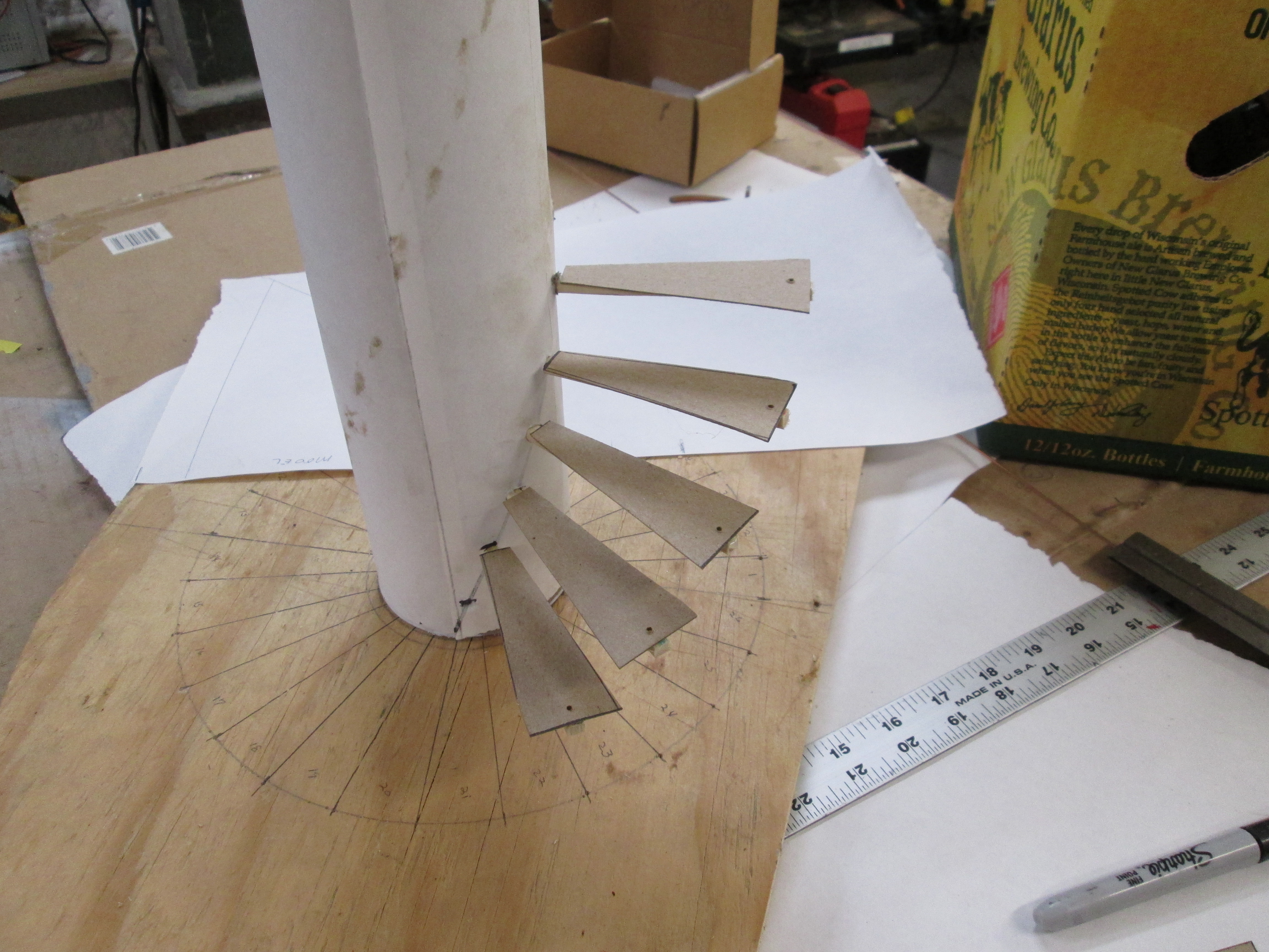
Lets get started with making the model. The scale for the model will be about


1/8" = 1" The tree trunk at the base is 30" and the height to where the first broken area starts is 19 feet. 

Working with some nice scrap plywood for a base and a 3.5" diameter shipping tube I had my tree trunk. After doing some research on the web for laying out spiral stairs I was ready to map the steps out. My stairs would have a rise of 8". The treads would be tapered from 4" where they will be mortised into the tree trunk to 12" wide at the outside end. They will be cut out of 2" thick Oak from the tree tops and other logs in the woods. A pattern was made on paper and wrapped around the trunk where the individual steps were marked and twenty-four 3/16" holes drilled. 

The 24 model stair treads are cut out of cardboard.


I hot glued the treads to chop sticks because the tapered end fit and held each step very nicely in the 3/16" diameter drilled holes. In the actual project mortis pockets will be cut 4" deep into the tree for the end of each step going up the tree. 


A 1/16 diameter hole was drilled into the wide end of each stair step. Through this hole a 1/16" diameter wire will be run. OxyAcetylene filler metal rods did the job very well. This simulated the 1/2" diameter rebar used in concrete work that I will use in the real project. Each step will be held up by the rod hanging down from the platform base of the Lookout/Treehouse tower.


 Here you can see the first few steps plugged into the "tree". Looks pretty good so far.


So with the platform base cut it was time to drill the holes where the rod hangers for the individual steps would go.


Here you can see the platform base in place and two of the 1/16" rod hangers installed.


A way to hold up and support the platform base will be needed. This will be made from treated 4 by 6's. There will be several things to consider here. First they cannot interfere with the headroom needed for the stairs. Any knee braces will also have to stay out of the stairway. Lastly the 4 by 6's cannot cover up any of the holes for the 1/2" diameter stair hanger rods. Modeling this out before actual construction will be a big help.

The opening in the platform base to allow for the required headroom needed for the stairs was another detail that had to be solved. Going with a minimum of 64" headroom with the 8" rise will require 8 steps to make it work. That is a bit more than 1/4 of the floor area of the platform base. For some reason when making the model I got it in my head that the platform base size was dependent on the stair hanger rods and made it this diameter. After some input from a friend I increased the diameter to 8 feet.


Here the model person (not to 1/8 scale) demonstrates the need for headroom opening that must be solved.


OK so after some trial and error modifications have been made to the 4 by 6 supports and the diameter of the platform base. This change in the platform base to an 8 foot diameter will allow for a narrow pathway around the stair opening.

Here the 1/16" filler metal rods have been run through the holes in the platform base and each stair tread. For the model I ran them all the way to the ground base. In the real project the plan calls for each 1/2" rebar having a washer welded to the end to be passed through the platform base through a star tread hole and then have a stop set-screwed below the tread supporting it. There's re-bar stop at the bottom of each stair tread. Thus hanging each stair tread from the platform base.


So there are a lot of moving parts to this project and they all have to work together to make it a success. Support of the platform base. Stair run, rise and head room. Support for both ends of each stair tread.


Nice view. I will be running the rods up along the stair opening to form a safety railing for the headroom opening. Will also be adding a wrap around bench for seating going around the "tree".


My plan is for the ceiling to be at around 7 feet. The sides, made out of treated 4 by 4's will be slanted out. There will be some sort of iron railing going around from post to post. This will allow for better viewing when sitting in the Lookout enjoying a beverage.


WHAT DO YOU SEE?


Thursday, December 15, 2022

Tipi project for fun

 Thought I would take on a new project and make it a Christmas gift for my neighbors 6 kids ages 2 to 12.

They are pretty handy and help a lot around their farm. This should be a good challenge for them to work together as each one will be given a few parts of the Tipi. If they follow the plans and pictures in the book and work together they will have some serious fun and make something they can all enjoy.


 The oldest boy will get the three main poles that form the tripod when tied together and the instruction for setting up the Tipi.

The next oldest will get the remaining 5 poles and that will make up the basic form as seen here in this picture.

Sarah will be given the canvas covering tied to the Lifting pole. This pole, when put in place along side pole #5 will fill-in the main framework. When the cover is unfolded and brought around the Tipi will look like this. She will also get the two poles used to control the smoke flaps. The flaps, normally left open to let out smoke are closed in this picture.


 The next in line will get a canvas bag filled with the stakes used to hold the outside edges of the Tipi down. His sister will be given a smaller canvas bag that holds the main Tipi line, smaller tie loops that are used to secure the stakes and the lacing pins that go up the center.

The little two year old, #6, will be given the door. So everyone gets a part and when all the parts are put together they will have a Tipi for everyone to play in. 

Their Dad raises bees so they will be able to waterproof the canvas this summer by coating it with a mixture made of two parts beeswax, one part boiled linseed oil and one part mineral spirits.

Merry Christmas


Saturday, September 3, 2022

Woven "Rainbow" Arch Bridge Project


Got a bit distracted last week. Saw this in the latest issue of my Timber Frame Guild publication and decided to give it a go. How would this design compare to the Town Lattice truss bridges I built a few years ago?

My idea is to experiment with this woven arch type bridge and if successful put together a 1/2 day learning experience for people interested in this unique design. They would build a small foot bridge spanning 20 feet out of 8 foot long landscape timbers at Shake Rag Alley arts center in Mineral Point, WI next summer.

The woven arch "rainbow" design is from China and over 1200 years old. Sometimes called a "chopstick" bridge to get the idea of how it is put together and how it works to span a distance and support a load I would literally start here.  After a trip to Walmart and getting my chopsticks I was ready to begin by following the steps shown in the pictures. This was much more difficult than it looked.

Several try and 20 chopsticks latter I had it. I splayed out the bottom legs to add stability but can now build this in less than 3 minutes! So now it was on the the next step. I would build my small bridge out of 8 foot long landscape timbers.

Just to keep interest I will show you the finished product. Amazing how there are no fasteners and this can hold 500 pounds!

Being a retired high school Tech Ed instructor and not an engineer I relied on common sense and experience as I experimented. First I designed and built a simple load tester. I modified and added a pressure gauge to my bottle jack. Each landscape timber was positioned in the fixture so the bottle jack could jack it up 1 inch from straight at rest. At this point I recorded the PSI reading on the gauge. The readings ranged from a low of 100 to a high of 600. The lower the PSI reading the weaker the timber's bending strength. Those were used for the lateral cross pieces.

The process starts like this. I clamped and tied the pieces together just to make things a bit easier.

Now this is a little tricky and having an assistant will make things go much smoother. My assistant took the form of two 5 gallon buckets to hold the two raised timber up while I slid the next pair of legs in and placed the next lateral across them. The bridge is assembled from the center out. The section on the right in the picture will end up being the center of the bridge and the two lateral cross pieces will then be level. 

This picture of the finished bridge might help you get the sequence of steps in mind better. You are going to be switching ends each time you add a section.

Here I have added a section on the left side. 

As the bridge grows so does the weight and it is time to replace the helper with a pair of step ladders, beam and two come alongs to raise the bridge legs and add another section.

You can see that in this first model I used a single timber for each bridge side. For the final run I doubled them up for more strength.

With the bridge assembled I wanted to see how much weight it could hold. This would be done by placing a swimming pool on top and filling it with 30 gallons of water (240 lbs).

I was quite pleased with the results. It held and with a 20 foot span brought the bridge height down about 4 inches as it tightened up. In this picture you can see two of the tie downs I attached to the bridge sides. This was done to stop the bridge from racking as there were no deck boards and the sides at the bottom not splayed out.

I took down and rebuilt this bridge three times. Making several improvements in strength and stability. I doubled the side legs and load tested it by filling two 30 gallon garbage cans with water (480 lbs) and splayed the bottom legs for stability. Here is the money shot! I still need to work on building a suitable hand rail system and attachment of it with clamps.

As an extra measure of safety because class participants will want to walk over a bridge they build I will be adding an A-frame type safety stop 6 inches below the center of the bridge to catch the bridge should there be a failure of any parts.


Friday, July 29, 2022

KidWind Guyed Tower Raising for Real


I hear it I forget. I see it I remember. I do it I understand. This is the mantra that I try to live by in teaching what KidWind is all about to coaches and students. Take the picture above for example. Most people would see this and say, "Oh, that's a windmill." From a teaching standpoint the questions might be, "What does it do? How do you get it up there?..."

A diagram like this might be in order to show the layout for the guy wires and what it looks like before the tower is raised. This whole process would take only a few minutes and make for small talk in passing. What I would call a "snack" in the world of education on the way to teaching a bit about renewable energy to a classroom of students.

In my mind KidWind is more about providing a "feast" for young students minds and hands to learn and understand what is being taught. This was the case for 24 high school seniors taking part in a two week on campus experience a few weeks ago that I worked with for a day at the UW Madison Wisconsin Energy Institute. Thanks to Allison Binder and Scott Williams invitation to help out.

The morning started out with groups of six students getting familiar with the rigging, terminology and process involved in raising a table top model wind turbine layedout in kit form like this. Everything was covered from a call to diggers hotline and wearing safety helmets. Safety was important from start to finish. The model generator was mounted, raised and tested for output lighting a small LED.

At the end of the hour each group had gone through the process twice. Once without the turbine to prove out the cable system and make any adjustments before mounting the generator to the tower. Finally their model turbine was raised by a small hand cranked winch and looked like this. 


OK time to put what was learned in the morning into practice on the real thing. 


After lunch it was time for the real thing. In groups of 12 they rigged the 9 meter tower and gin pole with a 300 watt Air-X generator for raising. Just like the learned with the practice model the tower was first raised without the turbine to prove out the rigging and make any necessary adjustments.

Mission accomplished! Now if you have or know of a group that would like to get this same firsthand learning experience let me know and we can plan it out. Learn about the future of Renewable Energy today!


Imagine the response these students gave on their first day back in school, to the age old question, "So what did you do over the summer?"    


Wednesday, June 15, 2022

New Duct Tape Roll List


The time has come for a change in tactics. Since 2004 I have been collecting rolls of Duct Tape from world countries. To date I have 91 rolls of Duct Tape in the World Duct Tape Collection. A coin, like the one pictured above will be engraved and given to anyone that adds a roll, to the collection of Duct Tape from a country on this list that I do not have. There are only 200 of these coins in the world. Here is the list of world countries I still need Duct tape rolls from to complete the collection. Send you roll and story of what country it is from, who you got it from and how you got it and I will send you your engraved 1 of 200 World Duct Tape coin.

Afganistan

Andorra

Angola

Antigua and Barbuda

Armenia

Azerbaijan

Bangladesh

Barbados

Belarus

Belize

Benin

Bolivia

Bosnia and Herzegovina

Botswana

Brunei and Darussalam

Bulgaria

Burkina Faso

Burundi

Cameroon

Cape Verde

Central African Republic

Chad

Colombia

Congo

Cot d'Ivoire

Cyprus

Democratic People's Republic

Democratic Republic of the Congo

Djibouti

Dominica

Dominican Republic

Egypt

Equatorial Guinea

Eritrea

Estonia

Ethiopia

Gabon

Gambia

Georgia

Grenada

Guinea

Guinea-Bissau

Guyana

Haiti

Honduras

Indonesia

Kazakhstan

Kiribati

Kuwait

Kyrgyzstan

Lao People's Democratic Republic

Latvia

Lebanon

Lesotho

Liberia

Libyan Arab Jamahiriya

Liechtenstein

Lithuania

Madagascar

Malawi

Malaysia

Maldives

Mali

Marshall Islands

Mauritania

Mauritius

Micronesia

Mongolia

Mozambique

Myanmar

Nauru

Niger

Nigeria

Oman

Palau

Panama

Papua New Guinea

Paraguay

Public of Korea

Republic of Moldova

Russian Federation

Rwanda

Saint Kitts and Nevis

Saint Lucia

Saint Vincent and the Grenadines

Samoa

San Marino

Sao Tome and Principe

Saudi Arabia

Senegal

Seychelles

Seria Leone

Solomon Islands

Somalia

Sudan

Suriname

Swaziland

Syrian Arab Republic

Timor-Leste

Tonga

Turkmenistan

Tuvalu

Uganda

United Republic of Tanzania

Uruguay

Uzbekistan

Vanuatu

Yemen

OK so if you are still reading this post lets look at the collection to date.

The question is, what do you do with the rolls of Duct Tape and how do you display them? 

For people new to the World Duct Tape Collection. The first goal was to get a roll of Duct Tape from each of the 50 United States. This took a few years but here they are displayed on the right around a map of the U.S. On the left is the first half of the Duct Tape rolls from around the world. As you can see this side is full and I needed to add another panel to the display unit.


This project has got me back on the hunt for the 100+ rolls that I need to finish out the World Duct Tape collection. With a new world map and some scrap wood I was able to frame up a third panel to hold more rolls of Duct Tape.

The three panels when displayed look like this. 

Now the display has a lot of other parts to it and when set up people can check out the details on each individual roll of Duct Tape in the collection. The log books record the date, pictures and story behind each roll of tape and the people that sent the tape to me. There is even Duct Tape from the International Space Station that is signed by 15 astronauts while they worked on building it!


And lastly the entire World Duct Tape collection needed to be self contained in a nice space saving package that could be transported and rolled around for display. 

If anyone is interested in having the World Duct Tape collection put on display please contact me.

For more details and the stories on the collection and rolls go to my ducttape2thefuture.blogspot  blog.

And if you want to take on the challenge of getting a roll of Duct Tape from the list of countries at the start of this post or know of someone that might be able to get a roll to add to the collection let me know. 

Rolls can be sent to Dick Anderson  11672 Center Hill Road Darlington, Wisconsin 53530