Well with the Timber Framers Guild 2017 convention right around the corner (May 19-21). And being that this year it will be held in Madison, WI (at the Edgewater Hotel). I have a peaked interest in attending this event to help in the construction of a 95 foot long walking bridge on site during the convention.
Sorry for the vertical formatting of the picture. Rotating pictures is one of my many shortfalls.
I have made contact with the TFG about this project and they passed my name along to Johnathan Orpin of New Energy Works and he got back to me with some information. In the mean time I decided to reverse engineer the bridge from the picture to see if I could better understand the bridges design and construction.
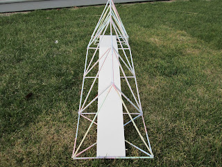
I decided to use soda straws and hot glue to construct a model. My first attempt was, shall I say, an enlightening challenge to say the least. The picture proved to be a bit of an optical illusion because of the 3/4 angle it was shot at. Good for selling a used car but not for getting design construction details. After some trial and error I had the basic concept and design of the bridge figured out. I went to work with my calculator and made a CAD drawing that was at a 1:12 scale. Keeping in mind the head clearance heights that would be needed I made the base of the main section (a three sided tower) 12 feet and then tapered it down to 8 feet two sections down. Keeping this all in proportion was the task.
Here is the 1:12 layout for the main tower section.
Soda straws were then pinned down and hot glued together. I learned that low temp glue worked best for this as the high temp glue took forever to cool down and burnt my fingers! One side down and two more to go.
The two sides of the main tower have diagonal bracing. The bottom panels in the real bridge will have cables running at diagonals. Another main tower is made just like this one and both will be angled up at 30 degrees to attach to a base. Each base is made up of a 4 sided equilateral pyramid. The intersection of the pyramid base and three sided tower is very interesting and I believe key to the design.
I took some pictures of the model from several sides to provide more insight into the design of the bridge. The walking surface touches the bridge at both ends and supported by rods coming up from the two cross pieces between each end. In the original picture I could see no connection between each side except at the top piece and the horizontal walking surface between the two halves. I believe having pieces here would increase stability.
Just for fun I had this poseable figure and thought it would give some perspective on head clearances and slope of the bridge incline. About 4 inches per foot, pretty steep and not ADA compliant. My model is only 54 inches long. If the real bridge is 95 feet long I would have to make the equaliteral pyrimiad much larger. Almost double? This will require some more thought and drawing. To be continued ...


No comments:
Post a Comment