Monday, February 28, 2011

Where did you put the Tree Nails?

Tree Nails or Trunnels or pegs as they are referred to in timber framing and bridge building are used to hold the joined members together.

 Trunnels used in timber framed structures (3/4" to 1"diameter) hold joined members, usually mortise and tenon joints from being "pulled" apart.

Trunnels used in the Town Lattice Truss building are significantly larger in diameter (1.5" to 2") because of the way the rotational load forces act against them.

We will place 3 Trunnels where the web lattice members intersect the top and bottom chords and 2 trunnels where just the web members cross. Placement of these "Tree Nails" needs to be carefully though out so as to cut through the minimum "thru fiber" of the wood for maximum structural strength.

The picture (above right) shows a full scale mock-up using 1" foam insulation. Three 1.5" diameter green foam Trunnels through the intersection of a  2"x12" bottom chord and 2x10" web lattice.


Where do you get tree nails? A tree nail factory of course. That would be Northcott Wood Turning in Walpole, NH. This family owned business makes wooden pegs by the thousands from many types of wood in various lengths and diameters. Who knew?  For the 3/8 scale model we will be using 5/8" diameter Maple dowels from the local hardware. In the picture above you can see the pre-cut pegs and below a 60 degree chamfer is being turned using the metal lathe.


As a side note, years ago, when learning the "cobbler trade" I came across a container of 1/8" square 5/8" long wooden pegs in my shoe repair shop. They were hard Maple and sharpened on one end. I asked my Finder what they were for and of course he told me, "wooden shoes". After he had his fun with me he demonstrated how they were used on leather soled cowboy boots in the arch area to fasten the outer and inner soles around the shank. When driven into a hole punched by an awl I was amazed! Their holding power equaled that of the soft iron clinch nails (see picture above). For real. I am not making this up.

Puzzler - How many different length Trunnels do you think will be needed to build the bridge?

Tech Vocab - Web    As in "Oh what a tangled web we weave...?"

Sunday, February 27, 2011

Welcome to the clamp factory...

I thought they must be kidding when in Milton's book, he said that they used three hundred clamps in building the 140 foot long Union Street bridge (Woodstock, Vermont 1969-1970) ! Each clamp was made of two pieces of 2" x 3" hardwood, and two 5/8" rods.  Do the math on that. How many board feet of materials just to make the clamps? How many linear feet of 5/8" threaded rod? A lot!

In the making of this 3/8 scale model I had to just about set up a clamp factory! No kidding. If you have been following along you know that 3 clamps are need to hold and align each joint in the chord lamination assembly. There are 14 of those. Then there are the chord ends, 8 of those. Then another 18 or so used to align and hold the second layer, web members and first chord layer together. Whew!

For the 3/8 scale model, the clamp material came from the "scrap" pieces ripped from the 1 x 6 boards used to make the chords (3/4 x 4.5"). Using a simple stop block on the miter saw the 3/4" x 7/8" strips were cut to length. Making a simple fixture (shown in the picture above) on the drill press each piece was located so the holes could be drilled. Not rocket science, but a good exercise in problem solving. We'll see how the students tackle this for the real bridge project. For the 3/8 scale model the long clamp pieces needed to be 6.5" long and the short ones 3.5" long. The lengths for the full size bridge clamps are pretty important and will need to be carefully calculated if they are to do their job and not get in the way during the assembly process. Something I appreciate so much more from the experience of building the 3/8 scale model.

Puzzler - So just how many feet of material will be needed for the bridge clamps? How many 3' long 1/4" threaded rods will be needed? 1/4" flat washers and nuts?

Tech Vocab -       1/2 -13  NC Thread

Saturday, February 26, 2011

Like they say in the TV commercial...

 That was easy! Just like Milton explained it in his book. "The third and fourth members of all chords will be applied as the first and second except that they will be plumbed on the upper edges from the members below and clamped securely as the work progresses. The same sawing up method is used throughout the chord building." Simple as that, well sorta.
 After chord layers C and D are clamped together where the ends meet the chord is straight. The end was clamped by several long parallel clamps to the first chord layers A and B.  You can see one of the long clamps in the center of the picture above. As the blue Quick clamp bends the chord more clamps are placed to hold it in place. Note: The smaller clamps next to the longer clamp are holding the ends at a joint in the chord layers A and B.


One more chord to go!

Puzzler - For the blog visitor from Australia - Would the camber for a bridge in the southern hemisphere have to be reversed?

Tech Vocab - Lathe - Chamfer - Trunnels


Thursday, February 24, 2011

A funny thing happens on the way to the top of the arc

In high school everyone in track knew that when it came to the longer races the outside lane was the best one to be in because you always started out way ahead of the rest of the runners. I made it a point to get the outside lane as often as I could. I must not have been that good of a runner because it seemed like they always caught up to me by the second or third turn of the race. Still it puzzled me why there wasn't more of a fight from the other runners to get this lane with this obvious advantage!

Well bridge building and putting the camber into the chords of the truss has shed considerable light on my thinking. Daha! The geometry involved is tricky but the up shot is that lattice spacing distance on an arc requires some adjustment on the top chord.  Milton Graton, a man of few words, in his book "The Last of the Covered Bridge Builders", explained it like this. "The base intersections of the lattice having been laid out for 4' on centers, a radius is projected from the extreme intersections to the top of the fourth chord. A measurement along the top chord will determine the amount of excess to be added to each 4' multiple without the inaccuracy of projecting additional radii." I have to admit I didn't even catch this little detail until the forth time I read his book!
 In the picture above if you look close the white nail to the right of the crossed tape measures is where the 4' center comes out if you just mark it off with a ruler on the top edge of the chord. Doing that really messes up the placement of the web members, especially as you get closer to the ends of the truss. It is an additive thing. Maybe it is like track lanes 2 through 5?
 Follow Milton's instructions and all is well. Web members nice and parallel. Remember there is a 1.125" camber in both chords.
And here you have it. What next? Two more chords with the same 1.125" camber. Any ideas on how to do it? In the book,  Milton explains it in one sentence. So how hard can it be? We'll see.

Puzzler - How do you think the camber will be put in the next two chords?

Tech Vocab - lattice, annual ring, parallel clamp

Tuesday, February 22, 2011

When do we get to work?

Throughout my career as a high school shop teacher this question always popped up within the first few days of the school year. My answer, "When you are ready. When you are, let me know. Tell me what work you will be doing (tools, machines, materials and processes you will be using) so I will know what to expect. Then go to work." Simple as that.

As with most complex projects there are several preparation steps that need to be performed before the "fun" begins. Building camber into the truss chords will be a process. Study the pictures for awhile and see what you can discover about this process. All input is welcome as this is new learning for me.


Here you can see the camber built into the bottom truss chord. The small blocks on the edges are holding the cambered chord in place on the false work and preventing it from springing back straight. This camber will offset the dead load weight of the bridge so there is no sag in the truss and bridge deck when finished and placed between the abutments.

 This would be much less complicated (for the builder) if I just get 40 foot long 4" by 12" timbers (nightmare for the sawyer). Instead good'ol Ithiel Town decided that each chord be made up of more available, common, regular size pieces of timber. His design calls for using several 2"x12" - 16 and 20 foot long planks. Staggered and lapped for maximum strength. Also, with this design almost any length truss chord could be built! Above you can see a pair of vertical clamps keeping the edges lined up and a single clamp going across the top and bottom to hold the pieces tight together. When the wood is arched to form the camber the butt ends will form a vee (wider at the top and tight at the bottom. To correct this a hand saw is ran between the joint. The saw kerf will cut the ends parallel to each other so they can be driven together for a tight fit top to bottom. Very important for the compression strength of the chord. 

Puzzler - How is this going to be kept in place during the assembly of the web and inside chord layers?

Tech Vocab - Jig,  Fixture,  False work


Sunday, February 20, 2011

Nothing to waste ...

Nothing to waste. Even the sawdust was put to use and a local hog farmer came and got it to use as bedding for his pigs.


I ask again, what do you see here? My mother, dear sole that she is, would say, "A mess and it needs to be cleaned up!" To me this is what I see, and feel and hear as the slabs crackle away in our Monarch combination electric range and wood stove. It make the kitchen toasty warm on a nasty winter day. 


Can report that in the week or so that the blog has been up there have been 156 page reviews. I look forward to your questions and comments to help make your visit worth while. Building a bridge to the future in South Wayne, Wisconsin will be a quite trip for sure. Keep watching our progress. Thanks

Button, button, who's got the button?

In drafting language the alphabet of lines refers to the "code" names of the different types of lines and how they are used. Dash lines are called "hidden" lines? These are used to show lines for what you cannot see? Say what? This kind of thing appealed to me in high school and I took a keen interest in "cracking" this code. There are center lines, section lines, dimension lines, leader and extension lines to name a few more. I have taken to using colors for the different lines as a help keep me on track when I am reading my "blueprints". At the risk of dating myself, remember the great smell of those dito-master copies your teachers handed out?  In the early days, copies of original drawings were made by a process that used special paper, light and ammonia (a foul smelling harsh chemical). In the development process the paper turned dark blue and the lines forming the drawing remained white! Thus the name "blue" prints and it stuck for a long time. 


Isometric (the pictorial drawing) and 3-view Orthographic drawing starts to get a bit more technical but, in my opinion, a need-to-know if you are going to build anything. Heck, I need to make out a list when I go grocery shopping and still mess up! Plenty of books and stuff on the web to help if you want to polish up your drafting skills.


The "button" we are talking about can be seen in the picture to the right. A hole has been drilled through the floor joist. A threaded rod passes between the inner and outer bottom chords of the lattice truss. The button at the very bottom is drawn up tight by the nut and secures the floor joist to the bridge truss. The same system will be used to attach the roof truss assemblies the the top of the bridge trusses.

Puzzler - What next?

Tech Vocab - Camber, Chord, Kerf to the line

Thursday, February 17, 2011

Things you should have learned in school...

One of the categories in Michael Feldman's, What-a-you know? public radio show quiz is, Things you should have learned in school. The question, What is the universal language that can be read and understood in all countries of the world? Answer,  Drafting. Show a set of plan drawings to any trades person in the world and they can get the message. Oh, there is a bit more to it but drafting skills and knowledge are key just like knowing the language of a specific country.

"Read" and study the isometric sketch and 3 view orthographic drawings pictured below. What do they tell you? What questions do you have? Make one.


I must admit to being a bit of a "dinosaur" when it comes to new technology. My drafting skills were gained using a T-square, Architects Scale, two Triangles and a mechanical pencil loaded with either 2-H or 4-H lead (really graphite). When the first Computer Aided Drafting (CAD) programs came out using a graphics tablet I found them more trouble that they were worth. Even when I started learning later generations of CAD I thought of them as not efficient. It took hours on the computer to do what I could do in ten minutes with my trusty T-square and triangles! I have since seen the light and error of my ways. There are 5 main steps in building any project: Idea - Sketch or Picture - Working Detailed Drawing - Bill of Materials - Plan of Procedure. Two of them require some degree of drawing or drafting skills and knowledge.  You don't have to be able to draw a "blue print" to be able to read one but I think it helps a lot. Imagine when filling out a college application and where it asks Foreign Language writing in yes, DRAFTING!

Puzzler - What are the Button Tie Downs for and how do they work in this bridge design?

Tech Vocab - Alphabet of lines

Wednesday, February 16, 2011

The scale of things...

Although Doyle, International and Scribner may sound like the names of three different types of bridge designs they are really the names for three different standard lumber measurement systems. If you want to learn more details about them Google - Number of board feet in a log - and read on.

If you have more time on your hands than you know what to do with (maybe one of the reasons you are reading this blog) or want to learn about Burr Arch Truss, Stephen Long's design, Howe or Pratt Truss to name a few. Google - Town Lattice Truss An Appropriate Bridge Technology for Developing Countries - a 2010 MIT thesis by Todd Radford.
Other sources:
US Dept of Transportation 2005 report - Covered Bridge Manual, good terminology reference.
Milton S. Graton's book The Last of The Covered Bridge Builders, a great story and pictures.

If a picture is worth a thousand words then it probably takes 1,000 words to explain it, right?
Well I will resist the urge and let the pictures do the talkin'. If you have questions I welcome them.

I have found in this process (Google - timber framed covered bridges - and click on the site that lists Darlington High School if you want to see the pictures and story on the first 3 bridges) that model and scale building to be the keys to understanding and problem solving before it gets to the real thing. Like Bruce, the student from Black Hawk High School working on this bridge said, "Make a mistake in cutting one of the real pieces and you have to cut down a whole tree to replace it!" He's right you just don't go to the local lumber yard and get a rough sawn 2" x 12" - 20 foot long board.

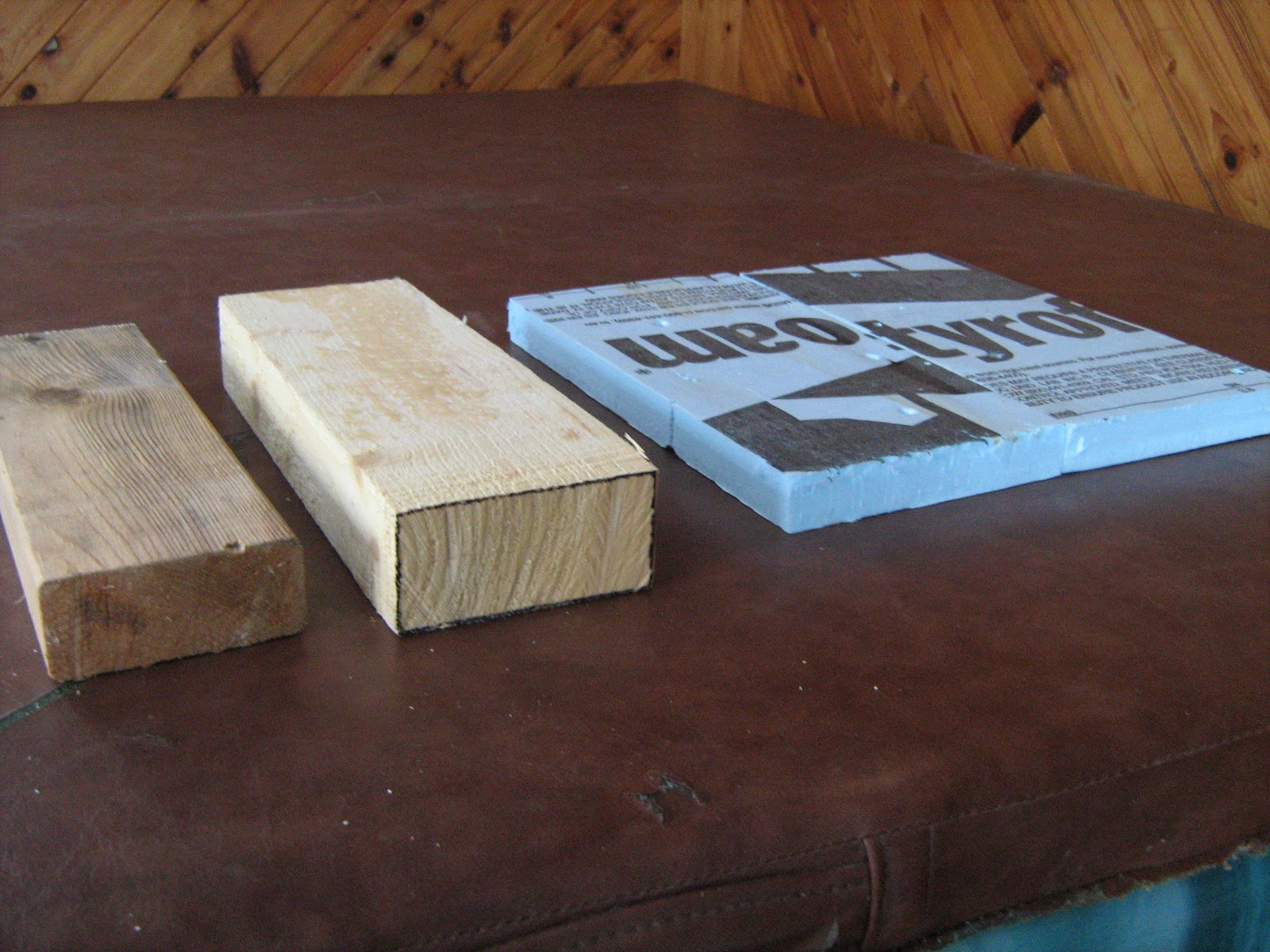
I have found 1/4" foam core board to be ideal material for model making. You can rip pieces on the band saw for 1/8 scale boards (works out nice as 1/4 represents 2" well). It cuts with a utility knife and can be screwed or hot glued together. You saw the results in the previous post 1/8 scale model picture.

The next step is to scale things up a bit to get more practice and the feel of working with real wood. Drawing and reading the scale plans, laying out the pieces, cutting and assembling them is great hands on work that teaches the important lessons and drives them home because most likely things will get screwed up. Nothing is as easy as it looks. You learn best the things you teach yourself. It is your brain that tells your hands what to do but there is no substitute for actual hands on experience. Finding the balance in the education of individuals is the tricky thing. Because I had some leftover rough sawn 2 x 6 material the model in the pictures above is full scale in board thickness ( 2" ) and 1/6 scale in board width and length. Great learning experience laying out and assembling the larger heavier material. The plan is to have Bruce dis-assemble this 1/6 scale model to "reverse engineer"  the process. Time permitting we may them transport the pieces to South Wayne and reassemble them at the bridge site to "proof out" our plans for the real deal.

Puzzler - Look at the pictures above and make a 3 view Orthographic sketch of some part of the bridge you see.

Tech Vocab - Orthographic, Isometric, View Projection

Stickers?

 When I was in high school, stickers where those pesky little picker things that stuck to your sleeves and socks when you were out hunting. A real pain. For bridge work stickers are the small pieces of wood placed between the layer of wood so that the air can circulate all around each board as it is dried in the heated Kiln (KD). It would be less expensive to just let it Air Dry (AD) naturally outside but that would take a long time and it would be difficult to lower the moisture to the 17% relative moisture that we require.


Up to this point we have spent most of our time looking a the raw material that will be used to built our 32 foot long Town Lattice Truss covered bridge. Five years ago I had no idea there even was such a thing. The only contact I had with covered bridges was from the movie Bridges Of Madison County with Clint Eastwood!  Now there seems to be no end to it. Ithiel Town, an architect by training patented his design in 1820. His design was pretty simple. Made with many similar size parts and requiring no complicated joinery and almost no metal fasteners it caught on. Another plus was the design was capable of clear spans of 100 feet. Also the length of the bridge could be extended by just continuing the lattice. In the pictures you can get a feel for the design and how to works.

The South Wayne bridge bridge will have three main parts. The deck, the trusses and the roof system. We will get into the details over the next few blog posts. For now, the deck will be 6' - 8" wide and 32' long. The trusses will be 8' deep when measured from the center of the bottom chord to the center of the top chord. The roof will have an 8:12 pitch with 2 foot over hangs at the eaves and 4 foot rake extensions on each end to protect the deck and bottom truss chords from the weather. We will use 4,750 Bd ft of pine and the green dead weight of the bridge will be a little over 11,000 pounds. Target date for completion is July 30, 2011. 

Puzzler - How many different bridge designs can you name?

Tech Vocab - Doyle,  International,  Scribner

Tuesday, February 15, 2011

What's cookin' ?

Believe it or not an 8" diameter log 10' long would contain about 41.7 Bd ft of wood.

Going back to the vocabulary and math parts of this if you recall the Board Foot is 1" thick, 12" wide and 1 foot long (144 cubic inches). Ugh! The dreaded volume problems of my math days. Thank you Mr. VanHalley.  So, taking the area of the log diameter * the height = volume, right? Well sotra. This should work.

 Any Log Diameter * 6.28 * Length of log in Feet / 12 = Board Feet of wood in the log

Give it a try. Maybe take a look at the trees around your home. What do you see?

Next time we will talk about efficiency and net product from our timber. Looking a board will never be the same for anyone that rides along on the "Bridge To The Future" journey as we design, plan and build Bridge #4 for the Village of South Wayne.

Puzzler - Determine the diameter log needed to produce a 4 x 4 - 10' long. Compare the gross and net board footage of the log required and the  4 x 4 - 10' long cut from it to determine the yield efficiency.

Tech Words - KD     AD    and  Sticker

Monday, February 14, 2011

Cant touch this... not or is it knot?

So the puzzler was to determine what circumference pine tree would be required to obtain a 12" square Cant? As with all technology I told my students that they should get credit for taking a foreign language. I mean after all if we learn "this language" won't we communicate, working and doing business with new people in a different culture and become productive citizens? 

Cant is a sawmill term used to describe the first timber piece that is sawed from the log as "slabs" are cut off. You have heard of the saying, "You can't put a round peg into a square hole?" Sounds like an Odyssey of the Mind (OM) challenge if you ask me. If you think about it all you have to do is cut off the sides of the round peg (log) to make it a nice square and the problem is solved!  Great care needs to be taken when positioning a tapered 10, 12, 14... foot long log on the sawmill to get the largest square Cant from each log. Then the sawyer must start critically thinking of how to turn the log and make the best cuts to get the desired boards from each Cant. More complex than it looks. All done with computers by the "real" lumber companies.  Maybe I'll promote the foreign language thing by adding a technical word or two to each new post. 

It would require a 37.7" circumference log to yield a 12" square Cant.
It took me years to realize that the "check mark" on my Casio calculator was for square root. I am a D- math person and I have the grades to prove it! The only thing I am worse at is spelling.

Some formulas and short cuts that could be used for the calculation -
- Square Cant size wanted * 3.14 = required tree circumference  needed
- Diameter of Log you have * .707 = Maximum square Cant size that can be cut from this log
- Square Cant size needed * 1.414 = Diameter of log to select

Puzzler - Calculate the total number of Bd ft of wood (not just the Cant)  in a log 8" in diameter and 10' long?

Tech Word - Wane

Saturday, February 12, 2011

The real size of a 2 x 4?

Lumber used in building Bridge #4 will be "rough sawn" and it is sold by volume and the unit measure for wood is the Board Foot (Bd ft). In most text books a Bd ft is described as a piece 1" thick, 12" wide and a foot long.  A simple formula is  Bd ft = (T" x W" x L' ) / 12.

So a rough sawn   2" x 4"  - 16'  board would = 10.7 Bd ft
   
Hopefully some readers were saying the question was poorly written because I did not specify if the 2x4 in question was finished dimensioned lumber or rough sawn lumber. What would its green dead weight be?

When I first started teaching the third time, in 2001, I went to the different skilled trades people in the area and asked them to give me the top three specific knowledge/skill things they would want a new, entry level, co-worker to know. The owner of the lumber yard said, "The real size of a 2 x 4." He was serious and I was stunned, but he was right on! To build Bridge #4 we are going to have to know a few things about the materials we use. How is knowing the nominal and actual sizes of wood, how much it weighs, how it is sold, etc. going to be of any use for things other than building bridges?

In the picture are examples of three different systems related to wood that need to be learned and  understood to successfully design and build our bridge. On the left your standard, finished 2 x 4. In the middle a rough sawn 2 x 4 and on the right a piece representing one Board Foot (Bd ft) of wood.

Puzzler - What circumference pine tree would be required to obtain a 12" square Cant?

Imagine that ...

One answer to the puzzler could be 1,427 board feet of lumber! This will be used for various parts of Bridge #4.

Thinking back to my classroom days the number one question put to most visiting foreign exchange students was, "How old do you have to be to drink in your country?" I am sure my students had a sound educational reason for asking. So along those lines, how much would 1,427 board feet of green pine lumber weigh? This will be important to know as we go about determining the load capacity of the bridge. I needed to weigh a few 8 foot long 4x4's and 6x6's to get some data. The digital scale used by the wrestling team came in handy for this. Although the density of pine varies I calculated the weight to average 2.35 pounds per board foot. I did a cubic foot of fallen snow too, but that's another story. All of the materials used in building the bridge will be considered the dead load.

I have a series of thoughts to cover as we go through the design and planning for this 32' Town Lattice Truss Bridge #4. I hope to engage the readers of this Blog to participate in 21st Century Career Technology Education as I see it. Experiences with, Critical Thinking, Problem Solving, Collaboration, Written & Oral Communications, Creativity, Self-Direction, Leadership, Adaptability, Responsibility and Global Awareness, to name a few. I challenge you to question everything. To comment and give specific useful, realistic, applications of these bridge building experiences to solve other related and unrelated problems in the real world as you see and experience it. This will be a "Bridge To The Future".

Puzzler - Calculate the number of board feet in a 2x4 - 16' long.

Thursday, February 10, 2011

First of many...

Greetings Bridge People. My friend Luke suggested that I Blog the building of Bridge #4. A 32 foot Town Lattice Truss covered bridge for the Village of South Wayne, Wisconsin. He said it was easy to set up a Blog and in my view "nothing" is easy. So I will take it slow and see if I can manage a picture or two and some "puzzlers" that will put you to the test. Enjoy and let me know what you think a community project like this can do for high school students.

So the "Puzzler" is. What do you see?