This post will provide the plans, instructions and materials list for building a 4 fan wind tunnel with a 48" opening similar to the type used to test student built wind generators in the Kid Wind Challenge competition.
It is important to note that the wind tunnel shroud is placed on the INTAKE side of the fans. Doing this will provide a less turbulent air stream of about 10 mph for testing student's wind generators.
NOTE: This is picture of the old design
Old design shown here.
Here you can see the finished product. This photo will be used several times in these instruction and will be helpful if referred to to study details and answer questions that will come up during construction. Note the large paper clips on the 1/2" EMT tubing at the opening. Note the 1" square blocks on the ends of the 1 1/2" PVC pipe arms that the 8mil clear plastic is wrapped around. Lastly notice the two large hand clamps in the upper left of the photo holding the plastic sheet where it joins together.
Note: No PVC pipe is used in the 2.0 design so no holes will be needed in the 4 corners.
HERE is the new 2.0 design. Simpler. More room and student/teacher friendly set up in less than 1 minute! No PVC pipe no EMT conduit no binder clips no wrapping of plastic no setup tools required.
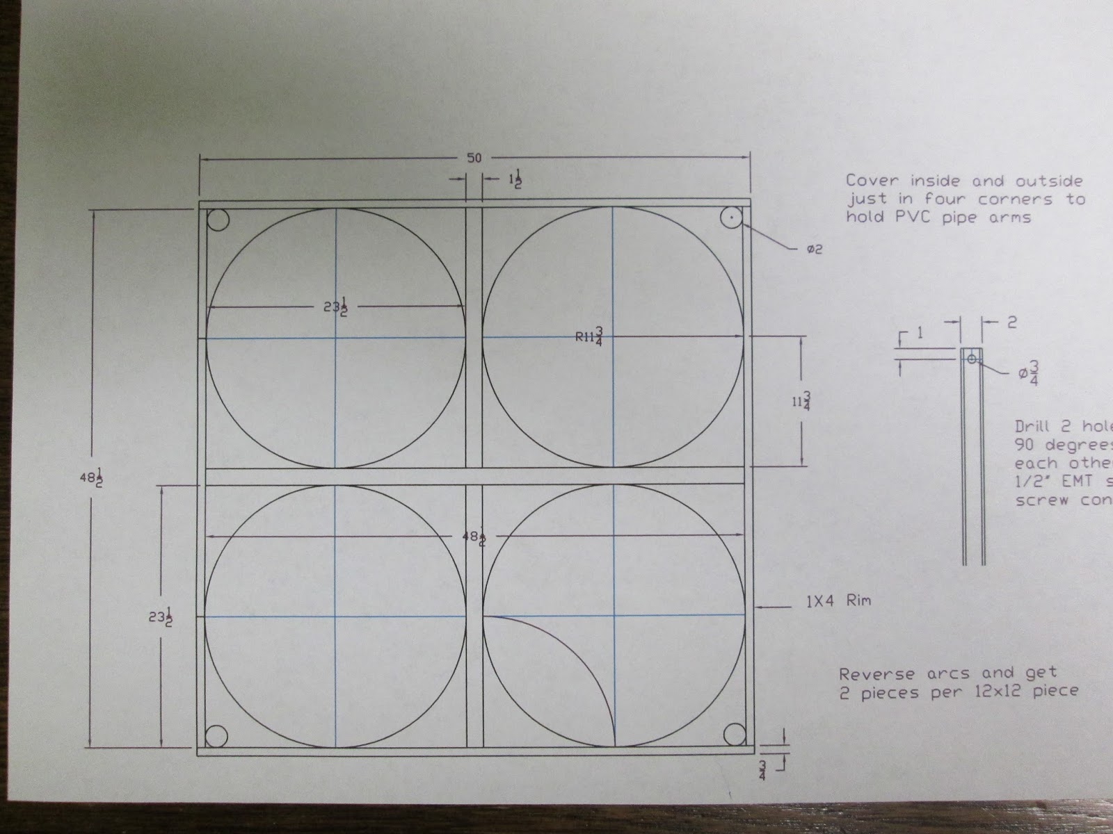
Here is the drawing. If you are a go-gitter like me and like a challenge than this is all you will need and go to it. If you have questions or need a few more details read on...
Here the materials list - Menards, Ace Hardware and Northern Tool were my sources for them.
- 1 - 3/4" handy panel 2' x 8' that will be ripped in half and cut to make the arcs in corners.
- 50 - 2" pocket screws
- 1 - 2x4 - 10' long
- 2 - 1x4 - 10' long
- 14 feet of 48" wide 8 mil clear plastic sheet
2.0 Design only covers three sides.
- 1 - 4 plug power strip with on/off switch
- 4 - Item Number 47051 Description RTN 22" Tilt Cooler $99 each. Northern Tool
NEW DESIGN 2.0 Materials for shroud frames - Rough Lengths
- 1 - 2x8 - 5 feet long
- 1 - 2x6 - 4 feet long
- 4 - 2x4 - 8 feet long
- 1 - 2x2 - 10 feet long
- 2 - 2x2 - 8 feet long
- 6 - 4" door hinges and screws
Tools list -
Skill saw
Assorted drill bits
3/8" hand drill
Drill press
Screw gun
Pocket screw cutter and screws
Band saw or saber saw
Remember what you are building? Lets get started.
Remember no PVC or EMT Conduit in New 2.0 Design
Well that was easy. If you got this far you know what I am going to talk about in the next few photos. If not then read on...
First you will want to rip the 2' wide 3/4" plywood into two 12" strips. Then cut twelve 12" squares (that should leave you a 4' long piece for the storage rack later). You are going to want to make a compass that will draw two 11 3/4" arcs on each 12" square piece you cut. These will be the fillers to go around the fans.
Then you will want to look at the print and cut the 2x4 and 1x4's the correct lengths. Using pocket screws assemble the 2x4's to make one half of the center cross like in the photo below.
You can attach the four plywood pieces (with pocket screws) as shown above and check the fit of one of your fans to see how you did. Note: these fans come with two plastic pieces for the tilt and lock mechanism. I removed them and it is a chore. You could leave them on and just place them in the corners at a diagonal if you want.
So moving right along. You have finished the other half of the cross and corner pieces. Now study the next photo and we will discuss the top and bottom pieces.
In this photo you can see that the outside corners have two pieces of plywood. Also understand that these corner pieces are ONLY attached to the top and bottom 1x4 pieces (NOT THE SIDE PIECES). They ARE NOT attached to any 2x4 piece. Later when the fans are put into the openings. Then you will screw them into the side 1x4's to secure them. Do not worry about attaching them to the 2x4's. Note: You will have to make a small notch in the four pieces of plywood at the center cross to allow the power of each fan to be routed through. You are looking at the back side of the wind tunnel and the power strip should be mounted right in the center cross area. Also for stability while building it is good to place the 2' piece of PVC for the axle in the lower hole.
NEW DESIGN 2.0 Simplified and Improved - read on
Lift up top frame then swing out each side frame. A simple pin in the front corners holds each side frame in place. Each plastic covered frame is hinged to the main fan box.
NOTE: You will also need to locate, layout and cut out some clearance notches in the tops of each SIDE FRAME so that when you swing the frames in for storage they will clear the spines of the hinges holding the TOP FRAME.
The key to construction is to extend each casing that the frames hinge to so that when folded each one will clear the other and fold flat. In this photo you can see that the top frame casing a 2x8 (extended the most because it has to allow for the other two side frame thicknesses) that the hinges are attached to. Facing you in the photo is the 2x4 casing used for the first side and hinges. The other side uses a 2x6 casing.
The drawing might be helpful. You have the main fan box in black. The
left and right side frames in green and
the top frame in red.
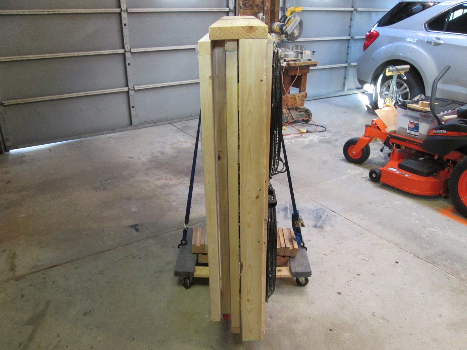
Here it is the NEW and IMPROVED 2.0 design. Easier to move, store, set up and take down!
ATTACHING THE 8 MIL PLASTIC TO THE FRAMES
The 8 mil plastic is attached to each frame by first hot gluing a strip of heavy picture frame mat material to one edge. Then rolling the strip to wrap the plastic around it. Then stapling through the plastic and mat strip to attach it to the frame. Next do the same thing on the opposite side, pulling the plastic tight. Repeat the process on the remaining two sides and you have one frame done.
I used a bandsaw to cut the 1/2" wide strips of heavy picture frame mat material.
Staple the plastic wrapped strips about every 2" along the outside surface of the frame edges.
Buy the time you get done with the third one of these you should have the hang of it!
If you have any questions or comments just let me know and I will happy to help a fellow Kid Wind'er out.