Taking a little break from the log cabin project to post some details on the Quilt Block Wind Farm being built here in Darlington, WI. Pretty big deal for a small town of just 2500 people. This project has been in the works on and off again for the past 10 - 15 years. EDP (Energies de Portugal) North America is the company backing the project. Forty nine 2 MW Vestas wind generators! Being interested in renewable energy and having a wind generator myself for over 15 years I have a keen interest in learning as much as I can about the process from the ground up. And I mean UP. Here are some facts about the project:
49 two MW Vestas wind generators
$3 to $4 million each installed
Total weight a whopping 380 tons each
Normal rotor speed 19 RPM
Cut-in speed 9 mph
Cut-out speed 56 mph
Nacelle 18' x 34' x 12' weighs 68 tons
3 Carbon fiber blades 160' long wt. 40 tons
300 foot tower 275 tons
Gravity Spread Base 40 - 60 feet diameter
40 tons of steel reinforcing bars
450 cu yd concrete
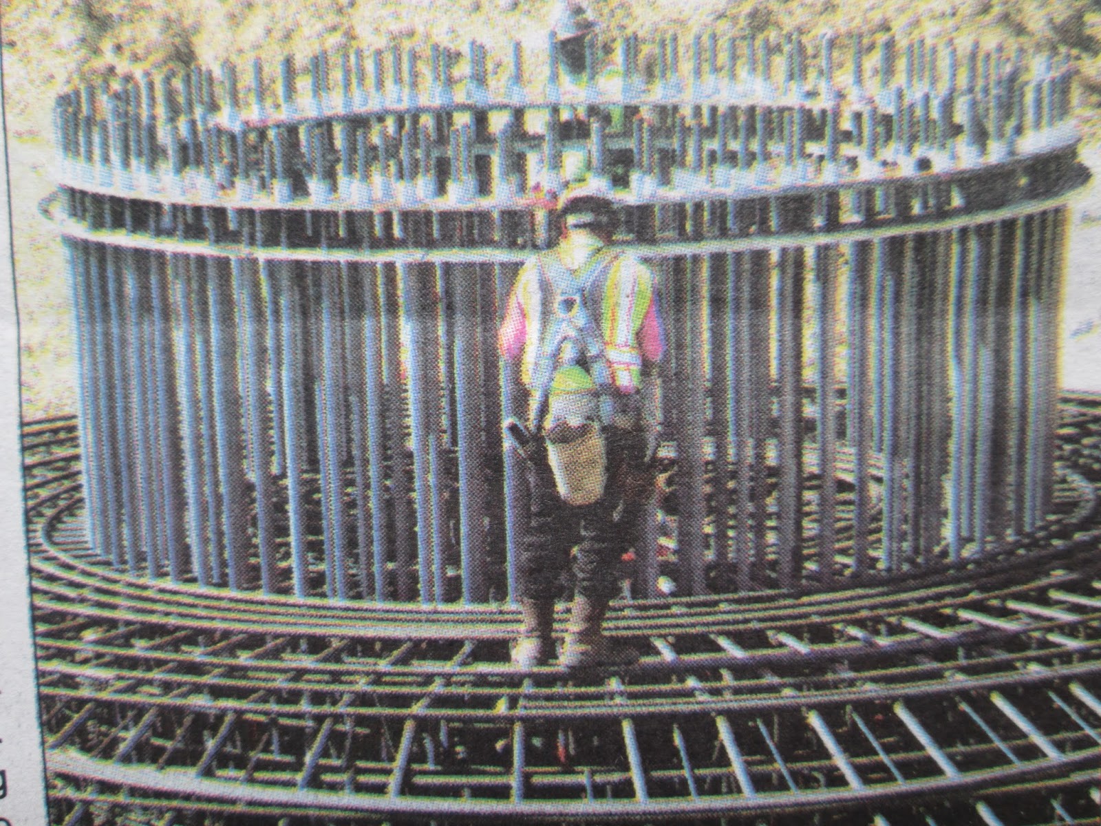
Step One The BASE
Here the concrete is being poured into the base. The form shape looks like the bottom of a wine glass. One down 48 to go...
Here you can see the mounting rings that hold and align the 140 - 1.5" diameter bolts that will secure the tower to the base. The bolts run thru the concrete to the bottom of the base.
When it is back filled this is all you see. The conduit for running power cables and communications wiring are in the center. There must be a spacer ring that is grouted and leveled placed on these bolts first as I have seen the base ring on one of the tower sections and it is only about 3" thick. Will have to check on this.
Step Two The TOWER
A small er 150' crane is used to set the first two sections of tower. The sections are bolted together by rings on the inside. They look be be 3/4" bolts and they appear to be placed every 6" on center around the ring inside. There is a built-in platform at each level for workers to stand when they install the bolts. I suspect that each year as a form of PM the bolts are checked for tightness.
With the first two sections in place it is time to bring in and carefully stage the rest of the components that will make up the generator. The Nacelle, the Nose Cone, the Blades and the final two tower sections.
What about getting to the top? Well it is a 300 foot ladder. Interesting point is that the ladder is held in place with magnets. Here you can see the blue colored magnets on the legs of the stand offs that hold the ladder. These are very powerful magnets and used because any welding could cause changes in the metal of the tower where cracks might develop causing a fracture in the tower and big problems.
At the base of the tower a level pad made of 8 x 10 timbers for the BIG crane has been laid. To the left are the final two tower sections. In the middle are the Nacelle and Nose Cone. To the right are the three blades. This arrangement is critical as the crane base will not move once the assembly process begins.
To get some appreciation for just how BIG these things are you need something to compare them to. Above you can see my wife standing next to one of the 160 foot long blades. Below I have parked my Mitsubishi MiEV electric car. Inside this Nacelle are the guts of the drive shaft, generator, gearbox, electronics and cooling units to keep the hydraulics cool. This weighs in at about 68 tons. My car weighs a little over 1.5 tons.
A note of interest might be that the blades are made of balsa wood, fiber glass and carbon fiber. They are made by laying many layers of the material in mold halves like the red one shown above for a 20 foot blade at the NREL labs.
The resin is introduced through a VIP (Vacuum Impregnation Process) where the layers are sealed in "bag" built so that a vacuum can be pulled and the resin brought into the many layers of cloth. Providing a superior product with no voids or air pockets. Her you can see the "plumbing" that has been installed for the resin to flow through.
Above you can see the third of four sections being lifted. Notice the top of this crane has been rigged to handle the weight with a braced tip extension. Also the crane cable has been ran through a four pulley block and from that four cables go to the top of the tower section. It takes about 15 minutes to raise the piece to the top.
Step Three Generator Assembly
The Nose Cone is bolted to the Nacelle and the assemble is mounted as a unit. The Nose Cone holds the three massive ring bearings where that the blades will be attached. The back of the Nose Cone is bolted to a massive plate that is connected to the main drive shaft supported in a pillow block type bearing. The shaft must be 10" to 12" in diameter I am guessing. This is connected to a complex gear box to increase the RPM and then the generator is connected.
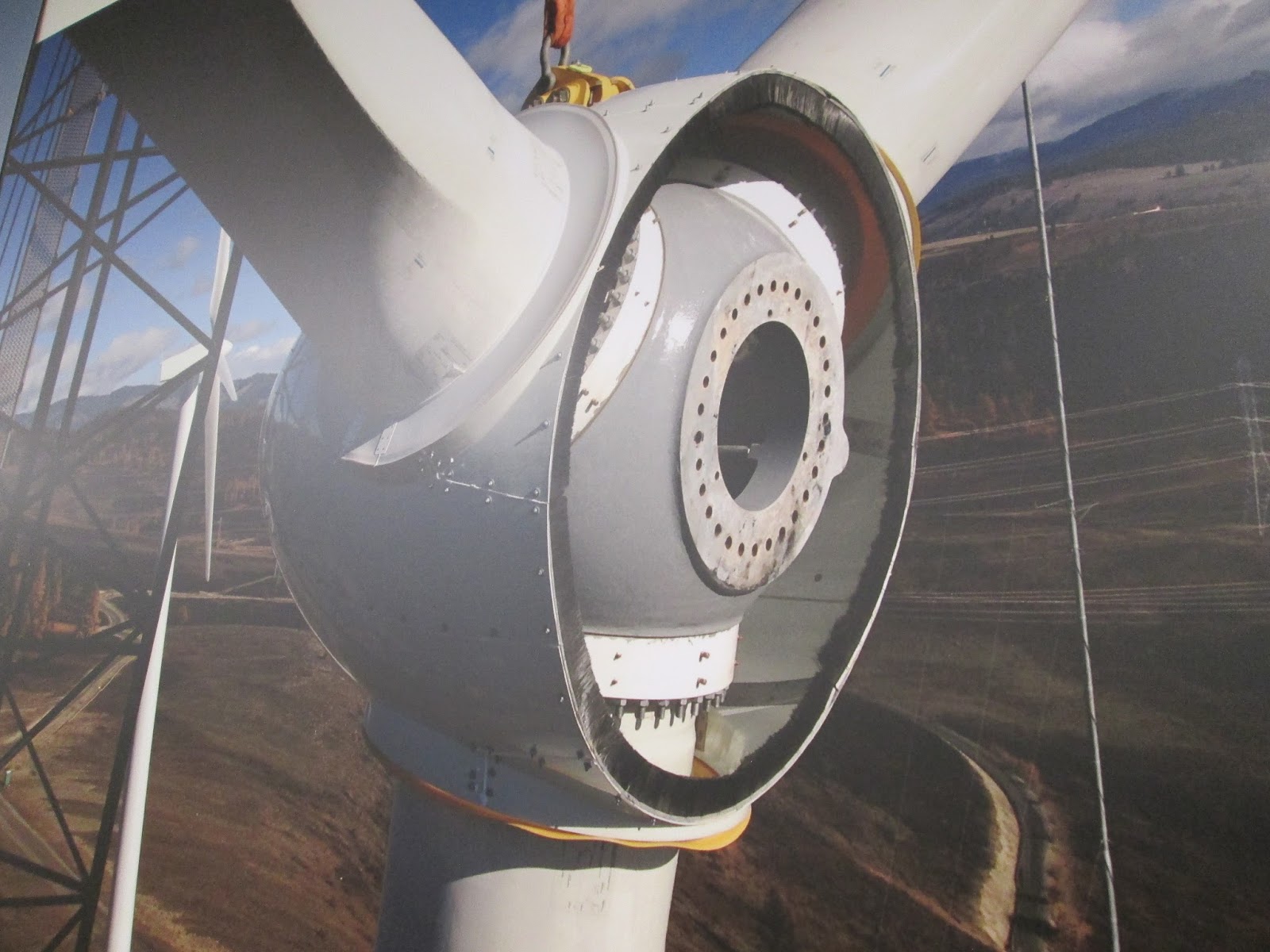
Taking a close look at the assembled Nose Cone and Nacelle and details of how the blade pitch is controlled.
Looking into the hole where the blade will go you can see the outer ring of bolts that secure the bearing to the hub casting. The ring of bolt holes where the bolts on the root end of the blade will go. The access plate that when removed will allow entry into the blade! And last the small ring of bolts that hold what I will call the pivot ball on the other side.
The theory of how this works is pretty simple. One end of the hydraulic ram is anchored in the nose cone the other end is attached to the pivot ball mounted to the blade mounting bearing. When the ram is retracted it will rotate the blade to the desired pitch. Note the access plate as seen from the other side you can see how thick the bearing is.
Maybe this picture (from another style turbine) will help get a perspective of what is shown in the photo above. Imagine the center hub with no blades on and you are looking up through the hole where the bottom blade would go.
Another feature of the Note Cone are the hydraulic accumulators for SAFETY. Each one stores enough energy to pitch one blade out of the wind three times and I am told there are four of these in the nose. Also it only take pitching one blade out of the wind to keep the rotor below the speed where it would self destruct. So they really have it covered when it comes to fail safes on shutting down a wind generator in case of a power failure. No power and the blades automatically pitch out of the wind and stall.
This assembly is then lifted to the top and secured with massive blocks and bolts. There is ring gear at the top and four hydraulic motors that can yaw the nacelle so as to point the blades into the wind for full power or out of the wind for maintenance and/or shut down. Again this unit is about the size of a school bus and weighs 68 tons!
Blades are the last piece of the puzzle. A specialized carrier (the size of a semi trailer) is used to hold and position each 160 foot long blade. Considerable thought goes into the placement of the blade in this carrier to insure balance and control during the process. It is hard to see in the picture but sticking out of the mounting end of each blade are what has to be 50 to 60 bolts that will be nutted up to secure the blade to its bearing race. Another item to note is the white rope below the blade. There are two of these and they are control ropes that are stretched out to the right and held by two skid steer loaders.
On a tour of the NREL (National Renewable Energy Lab) I got to get up close and personal with the root end of a blade from a 1.5 MG generator. Here you can see the bolts that will attach the blade to the hub.
The Nose Cone has been rotated to horizontal and the ground ropes can be used to control the blade and with the crane operator this blade can be aligned just right (like threading the needle 300 feet in the air). It is a wonder to watch such precision and control of such massive weights. There is a crew of assemblers waiting in the Nose Cone. You can see the hatch opening. Also you can see a rope that is attached to the end of the blade and the carrier (sort of a loop). The assembler will use this rope to pull the blade the final inch or so into the mating ring of holes. If you have ever changed a tire and tried to line up 5 lug bolts with a 75 pound tire in your hands you can appreciate what is really going on here.
It took about an hour to get the blade on and unclamp the carrier.
If you look closely at these two photos you can see that the blade has been rotated 90 degrees. At this point you could hear the sound of more impact drivers tightening more bolts. My guess is that the best tightening takes place on the bottom half due to the weight of the blade and also would put the bolts at a more reachable height. Will have to ask more about this procedure. Each of the blades has a hydraulic ram attached to it that is used to control the pitch of it for efficient use of different wind speeds.
With the first blade attached the Nose Cone is rotated and the process repeated two more times. Lift, attach, rotate, repeat! Pretty well oiled operation. You could tell this was not their first time doing this.
And then it was complete and the giant crane moved off over the access road to another pre-stagged
location to do another one. One down 48 to go! The crane moved at a snails pace but it was rock solid. The more that six foot diameter block at cables end never even swung.
I welcome any and all questions and will do my best to seek out the answers. The more we know and understand this technology the sooner more will get on board. The renewable energy train has left the station in Darlington, Wisconsin. 53530