Sunday, September 15, 2024

Balancing - To add weight or remove wood?


In life having a "balance" is important and takes considerable time and effort. So it is with getting a balance for hand made wooden turbine blades. Here is how I went about it. I learned there are different kinds of balance. The first balance I did was to make sure that all three blades were angled 120 degrees apart. 

The next balance would be for the weight of the 3 individual blades. I explained in an earlier post that I tried to achieve this by cutting the 3 three blades from one 18 foot pine 2x8. My thinking was that this would insure the density of each blade would be similar. I weighed each blade before and after carving. They were very close with one heavy one.

After carving two of the blades were within 10 kg of each other and the one heavy blade was 200 kg over their readings. My question was do I add weight to the lighter blades or remove wood from the heavier blade?

Here is a picture how much of the pine wood weighing 200 kg looks like.  I would have to remove this much wood from the heavy blade. The decision was easy. No way! Add some weight to the two lighter blades would be done.

To do this I would mount the blades to the rotor hub and then hang the assembly at the center point. I would place a string level on each blade. Moving the weights along the length of the blades to get a balance. This was tricky with three blades. Try it if you don't believe me. When I had determined the correct weight and placement along the blades the question became what material to use and how to attach the weights to the blades. My thinking was to get stainless steel punched out the correct diameter for the weight I needed. Then counterbore the blade and screw them on. After a long discussion with Dan B. I came to my senses and learned from his considerable experience that attaching lead weights to the edges of the blades near the root end would be a far superior solution to my blade balancing problem.   

Another balance issue to consider is that of the blades being in the same plane when rotated. This was checked by rotating the balanced blades and marking each tip height. 

OK then lead weights it would be as shown here screwed into the sides of the blades.

You can get lead from your local tire shop but, where do you get lead weights the size you need? You make them.

And just when you think it is going so good. I wanted to make one more balance test with the blades this time in the vertical position. This would require a new center plug in the rotor plate and axle mounted between two 8 foot step ladders. In the process of trying to raise the 50 pound 3 blade rotor I discovered that I didn't have the room in the shed I needed and would have to take it outside. As luck would have it the trailing edge of this blade went into the seam of the cement floor and when I lowered it I cracked it. My brief response was, #$%&@@!

The feeling that one gets from designing, building and testing something like this is well worth the time and effort. The rotor balanced with the blades in any position. 

The lead weights did the job. Thanks Dan B. Now I will prepare for their mounting on my Enertech 1500 up the tower.


Friday, September 6, 2024

Finishing the blades


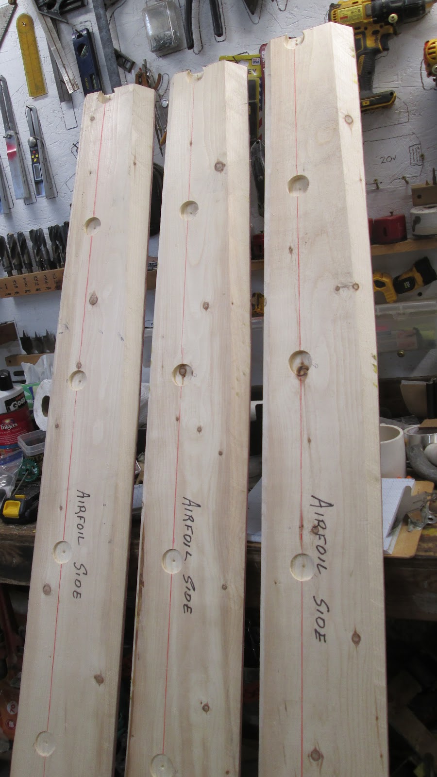
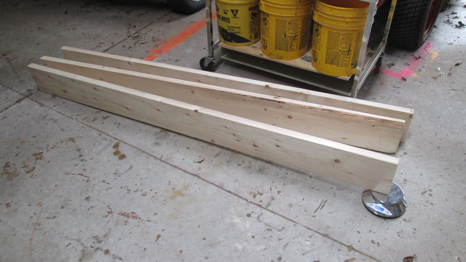
With the blades all carved out it was time to weigh them. Two of the blades weighted in at about 7 pounds each. The third one was 7.4 lb. This will be dealt with later in the process.

Knots were going to be a problem as one or two of them already came loose during the carving. My solution for this was to drill a hole at the edge of each knot and then put in a stainless steel screw. The threads will cut into the knot and the blades material holding the knot in place. 


Using a hand hacksaw I cut off the head of each screw and any part that was sticking out the other side of the blade. Then each screw stub was ground flush to the blade surface.

Now it was time to drill the mounting holes in each blade. This was complicated as the blades not only had to fit the mounting plate of the hub still up on the wind turbine the 3 nose cone mounting holes had to line up and fit. Tricky at best.

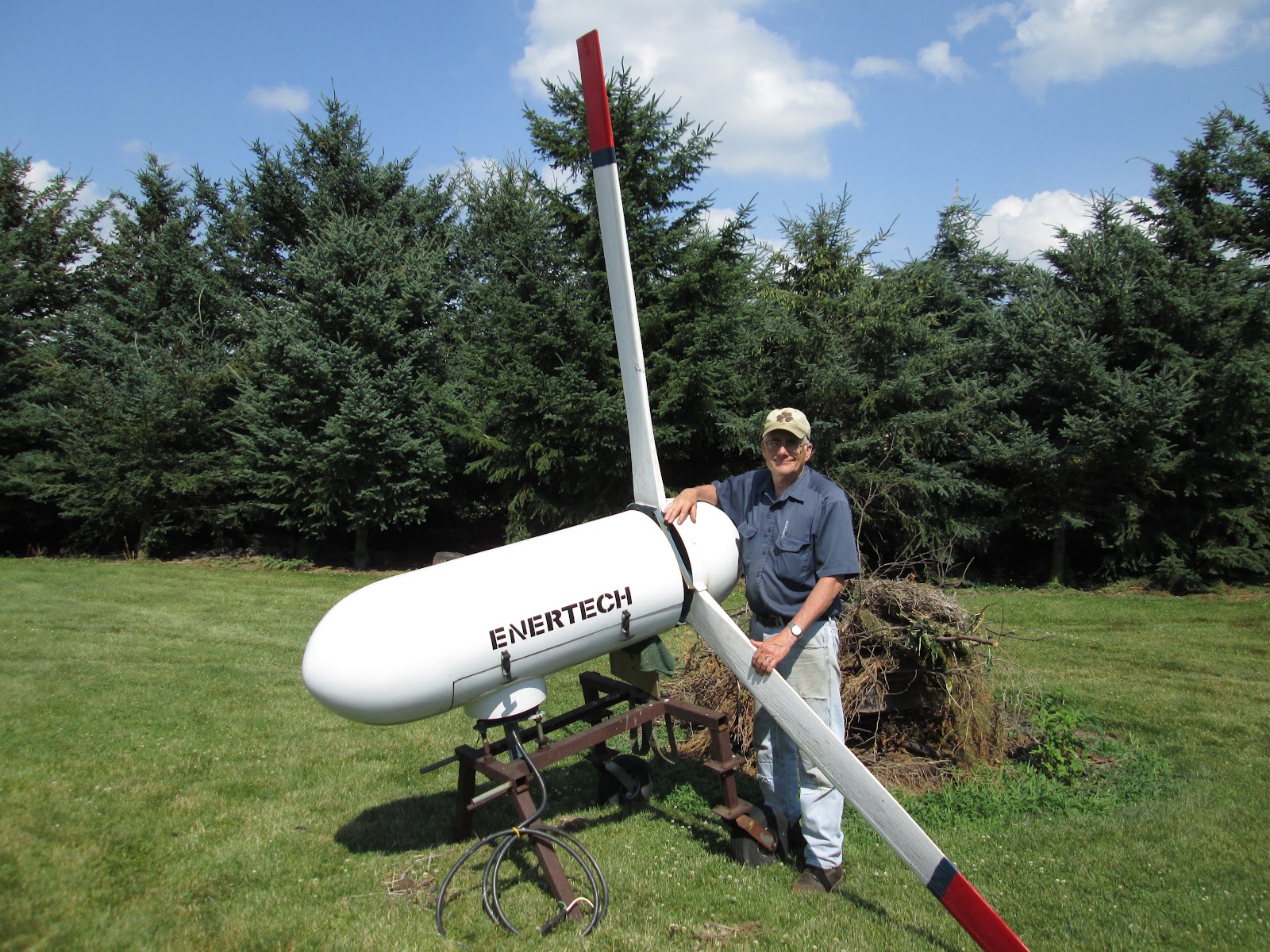
The back story. The used Enertech was a $300 "boat anchor" when I got it 25 years ago. The windings on the generator were toast and the blade mounting plate had a crack in it. At the time I was working on another renewable energy wind project and wanted to get a wind anemometer for the Scales Mound school where I was teaching. An article in Home Power magazine on a Wind Explorer data logger made by NRG systems caught my eye. I decided to reach out and contacted NRG systems to see if they could help. To my pleasant surprise the president of NRG, Dave Blittersdorf emailed me he would be happy to send a Wind Explorer unit to me free of charge. I was thrilled. I told him about my Enertech rebuild project and the problems I was having because Enertech had gone out of business. Dave told me not to worry, he could help because he had bought out the inventory of Enertech when they closed. He had a mounting plate and would send it to me for $25. 

So what to do with the old blade mounting plate? For years it "slept" in my iron pile. 

Then one day I needed a base for one of my metal yard art sculptures. As the plate was welded on I thought I could take some measurements and make what I needed out of a piece of plywood. Well I tried that and have another story to tell about measuring angled pieces like this.

Anyway after scrapping out the plywood I took another path. This would prove to be a much better solution and more accurate. 30 minutes later, wala I had my plate with blade mounting holes to use as a guide.

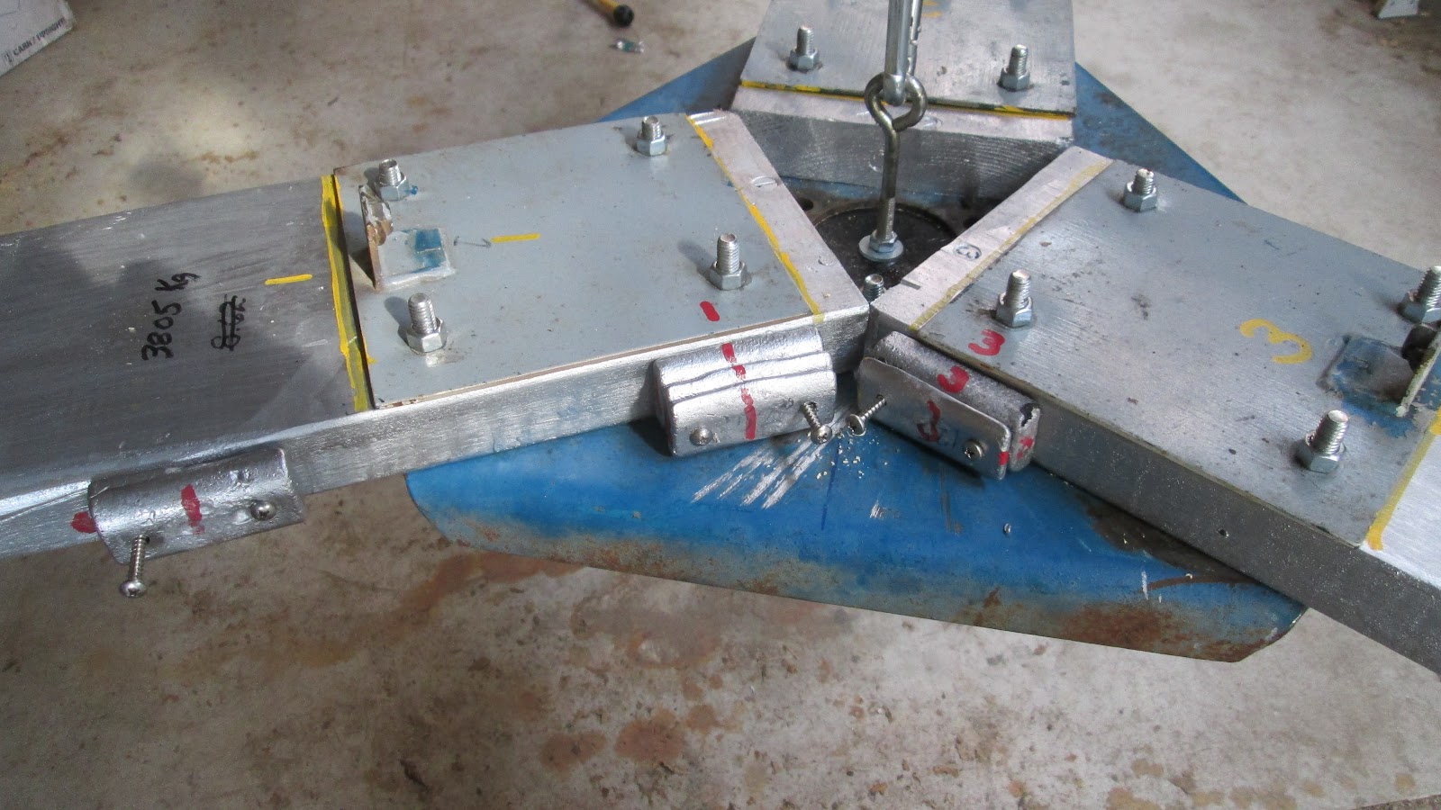
Each blade on the Enertech has a plate like this so I used it to locate the four holes. The angle iron piece at the bottom edge has the nut welded into it for the nose cone mounting screw.

 
Blades drilled, plates attached and the extra mounting plate with a plug installed in the center hole.

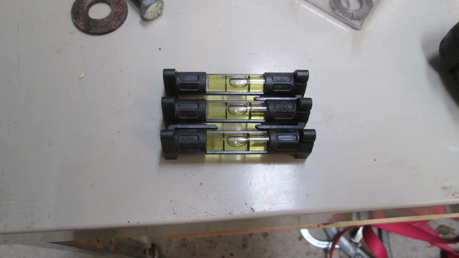
The mounting plate is suspended by the eye screw in the center. When the blades are attached I will be able to balance the assembled rotor.

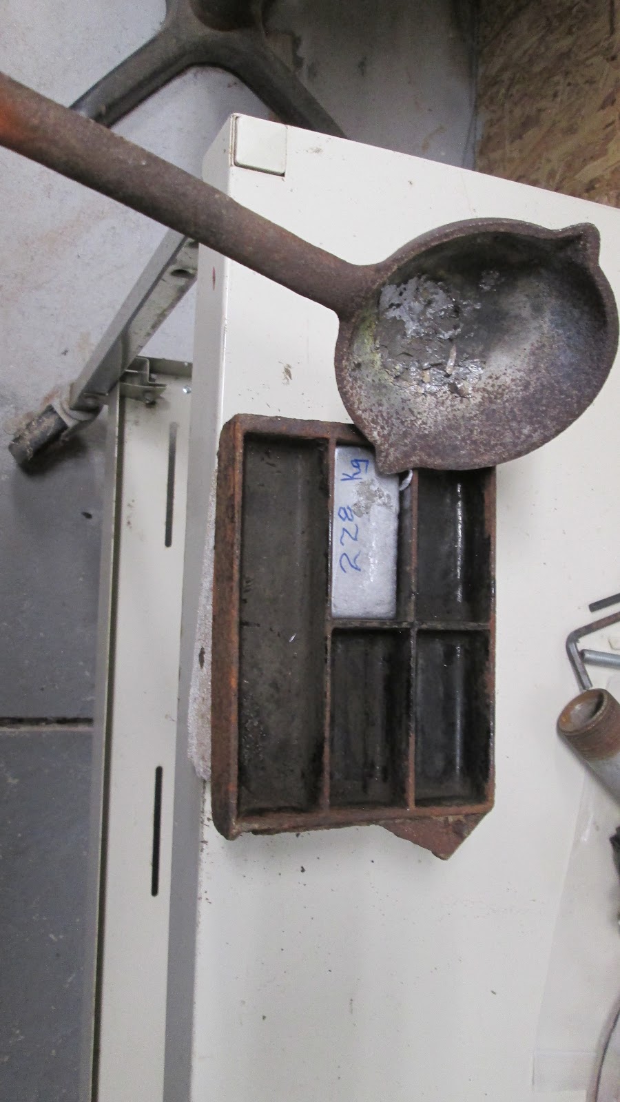
I took a page out Marcellus Jacobs, father of the modern wind turbine, playbook and finished my blades with Aluminum plant. 

Next up, the balancing act.


Thursday, September 5, 2024

Shaping the blade airfoil side


So now that the wind ward side of the blades has been cut with the proper pitch it was time to cut and shape the airfoil side of the blade.

With the profile of the airfoil shape drawn in the excess material that needed to be removed could be seen. 45 degree angles were marked on the leading and trailing edges. 

I decided to cut the bulk of the material off with a portable circular saw.

Since the thickness of the blade tapers from the root to the tip I followed the line marking the trailing edge of the blade.

Looking at the tip of the blades you can see the amount of material removed by the rough cuts. The blades will also taper from 1.5" (40 mm) at the root down to 5/8" (15 mm) at the tip.

Five depth indicator holes were bored from the tip of the blade to the root to mark the taper. The holes were drilled at the thickest part of the airfoil shape.

Hole depths went from 0 mm at the root to 22 mm deep at the tip as shown above.

Using my rabbit plane I cut a groove from the tip of the blade to the root. This gave me the line (surface) I needed to get the correct taper of the blade. In this picture you can see the material that needs to be removed above the airfoil shape at the tip of the blade. The amount of material needing to be removed would decrease as I worked toward the root of the blade. The amount of decrease would be indicated by the decreasing depth of the rabbit groove I cut. 

To speed up the process of removing this material I used a tool that served me well when chainsaw wood carving log sculptures. This blade made short work of removing the excess material from tip to root giving me the taper of the blade but not the airfoil shape.

With the correct taper cut I could now switch back to the jack plane and carefully shape the airfoil on each blade.


Wednesday, September 4, 2024

Blade layout and pitch

 Having the old blade to use as a pattern is a big help. The flat or pitch side of the blade ends are in the same plane. Here you can see the leading edge of the blade. The airfoil side is to the right. The drop or pitch will be cut into the blade on the left side.


I needed a pattern to mark out the drop and decided to make one out of a piece of thin metal strip material I had. This was fastened to the trailing edge of the old blade.


I then traced the drop distance onto the metal and cut this material off making the pattern I could trace onto the new blade blank.


With the metal pattern attached to a blade blank's trailing edge I could trace the drop onto that edge. I marked the edge with X's that defined the area to be removed. Removing this amount of material from the trailing edge up to the leading edge would give me a pitch of about 7-8 degrees near the root and diminishing to zero degrees at the tip. 


Made another metal pattern for the airfoil design at the blade tip.


Clamped the first blade blank to my bench and went to work with my trusty jack plane. On the trailing edge of the blade you can see the layout lines. The top line is the drop giving the pitch to the blade. The line below the drop line sets a thickness of 3/16" for the trailing edge. The two red lines on the surface of the blade on the top right define the area where the leading edge will be rounded.


The drop material has been removed down to the line. The blue line and X's on the bottom marks the material that will be removed at the trailing edge on the airfoil side of the blade. This all makes more sense after you have read Dan's book a few times and made a blade or two out of styrofoam. First cut has been made. Now I will do the same to blades two and three. Then begin work on the airfoil sides. 
   

Monday, September 2, 2024

Enertech Blade Replacement Project


Twenty five years ago I drove up to Mick Sagrillos shop and picked up a used Enertech 1800. It was the high point of my quest for a wind powered generator that began in the 70's following  Mother Earth News with my home built 12 volt car alternator and blades made out of styrofoam insulation. 

The learning experience continued and advanced with help from Home Power magazine and the MREA (Midwest Renewable Energy Association).  It continues to this day.

Fast forward to 2021 Covid was ending and so was the life of my turbines blades. One of the blades had rotted off at the root. I removed the other two thinking I would get some wood and make replacement blades. I had read Dan Bartman's book and had the original blades for patterns. How hard can it be? Lets find out.

First stop was Menards to get a 20 foot long 2x8. My reasoning was to get one piece of wood and cut it into the three lengths I needed so they would have the same weight. (Should have brought my saw and cut it at the lumber yard.)

Two cuts later at home. I was looking for a piece that had vertical grain like quarter sawn but instead went for a clear piece with very small knots and flat grain or plain sawn piece.

The next step was to get some data on the weight of each piece. My cheap'o digital scale only went up to 7 pound so I had to improvise.

Very happy with the slight weight differences in each piece.

Making blades for a wind turbine, how hard can it be? Lets see...